BILT Speaker

BILT Speaker
RevitCat - Revit Consultant
Showing posts with label Divided path. Show all posts

Wednesday, 30 April 2014

Reasons to be Cheerful - about Revit Adaptive Components

Why did I publish a list of Reasons not to use adaptive components in Revit when I have previously published so much good stuff about them?  Well, it is because they have so much potential to allow us to do wonderful things in Revit - but it is largely unrealised potential for the average Revit user.  We need Autodesk to remove those "reasons" so that we can start to use adaptive components in everyday life, instead of just for specialist situations.

However, Adaptive Components can be used to do amazing work, so I need to redress the balance of the previous negative post with this list of positive reasons for their use.

Adaptive components started out life as a special tool for filling in edge pieces on mass surface patterns.  From there they have developed into a totally different beast.

  • Multiple placement points can be used to control orientation in 3 dimensions (unlike line-based families that can only rotate in 2 dimensions).
3 point adaptive tubes
  • Multiple placement points can be used to control the scale of many and varied parts of the family - just by the spacing of the adaptive placement points
3 point adaptive tube placed at varied angles and lengths
  • Adaptive points can snap to elements in 3d space, and remain linked to the vertices of those elements - which become hosts - perfect for tensile structures (just remember never to delete the hosts):

4 point adaptive component tensile canopy

  • Points!  These are wonderfully powerful elements in the mass/adaptive family environment - I miss them back in the traditional family editor.  They can be used to host and control other elements, once you understand them.
  • In v2014, three points can host an arc by start, end,radius - this cuts out lots of trigonometry and formulas

  • Points can also be hosted on lines, arcs, etc - they then take on different, very useful properties 
Points hosted on lines and intersections
  • Points can be used to control rotation within families.  Wow, no more reference lines and dodgy angle parameters!  thanks to Alfredo Medina
 
  • Divide Line & Surface commands are available in the mass/adaptive family environment - they cut out a lot of the work we previously had to do with formulas.
 
  • Repeaters - the adaptive version of the Array command, but oh so much more powerful than traditional arrays.
Calatrava - Station roof support using nested repeaters, hosted on divided paths on geometry hosted on points!

Now, if only we could use all this stuff in the traditional Revit family editor . . . . . or else have all the traditional functionality in adaptive components . . . .  then Revit would really rock!

Sunday, 3 November 2013

Circular repeater geometry in Revit

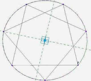
In previous posts I have described how easy it is in Revit to use a circle as a rig to host regular geometric shapes like squares and hexagons.  It occurred to me the other day that circles would also be ideal hosts for parametric stars;  put that together with Repeaters and you get some interesting possibilities . . .

Here is how to create a parametric star:
  • Create a new adaptive component;  
  • Place a point at the origin; make its reference planes visible
  • Set the horizontal ref plane as the work plane
  • Place a reference line circle onto the point
  • Make its radius dimension into a parameter
  • Select the circle
  • Divide Path
  •  It will create a divided path on top of the circle with 6 nodes
  • Create another Adaptive component
  • Place two points, and make them adaptive
  • Place a line between the points, remembering to enable "3D Snapping" first
  • Save the second family (eg. as "AC 2pt Line")
  • Load it into the first family
  • Place one of the components onto two non-adjacent nodes
 
  • Select the two-point component and click on the Repeat command
  • You should end up with a triangle
  • NB.  if you placed the two-point adaptive line component onto adjacent nodes you'd get a hexagon
  • Actually, a triangle is only half of what we want, but we need to backtrack to get the correct result - so, UNDO the repeat command
  • Place a second two-point adaptive on alternating non-adjacent nodes
  •  Select both lines and click on Repeat
  •   
  •  You should end up with a six pointed star, which is now a "Repeater"
  • Select the divided path, and change the number of nodes to 5, giving you a five pointed star
  •  Change it to 4, which gives a cross (not so useful)
  •  Change it to 3 for a triangle
  •  Change it back up to 7
  •  And then to 8 - this gives an eight pointed star that could be useful in tiling patterns when repeated itself on a divided surface
  •  As the number of nodes increase, the shape becomes closer to a circle
  • Now all you need to do is turn the number of nodes into a parameter to get yourself a one-point adaptive parametric star component
  • Oh, one more thing - you need to make the nodes of the divided path not visible otherwise they will show up when this component is placed in a project or another family


How useful is this going to be?  We'll investigate that in a future post . . .
Here is one possible use - geometric patterns


Saturday, 14 September 2013

How to Indent a Revit Repeater on a Divided Surface

In a recent post by Andy Milburn over on Shades of Grey, he mentioned that it is not possible to indent the edges of a divided surface.  Well, that is absolutely true - Divided surfaces are unlike divided paths, which have an indent setting so that you can push the start or end nodes of the path in from ends of the underlying path.
Divided Path indent settings

The implication of this is that when you use a divided surface to generate a "Repeater" in Revit, the repeated adaptive components will overhang the edge of the divided surface.   In the example below, a one point adaptive component is placed on a node of the divided surface, then repeated - since the adaptive component consists of a cylindrical extrusion centred on the point, it is repeated to all nodes of the divided surface.


Since you cannot indent the edges of a divided surface, how can you prevent the repeater overhanging the divided surface?  If you made the extrusion offset from the adaptive placement point you could make it indent on one or two sides of the divided surface, but then it would overhang even more on the other sides.

However, in Revit there is usually a way to achieve what you want, so I attempted to find a way to indent the repeater, if not the nodes of a divided surface:

How to Indent a Repeater Pattern

You have to use some tricky thinking, and control where the repeater components will land - and prevent it from placing any part of the extrusion in the adaptive component on the edge nodes.
One way to do this would be to create a four point adaptive component:
  • First create a new adaptive component and place four points in a square arrangement
  • Make the points adaptive
  • Join the four points with four reference lines
Now you need to set out a centre point to host the geometry so that it remains centred whatever the arrangement of placement of points
  • Place four more points on the mid-point of each reference line (watch for the triangular snap symbol
  • Join those four points with two more reference lines
  • Place yet another point on one of the central lines
  • When you select the point, it will have an option (on the Option Bar, no less) to host it by intersection
  • Select that option, then pick the other central reference line
  • It will move the point to the central intersection.
  • NB. On reflection, you could skip the last four stages and just have one central linking reference line with a single point on its mid-point.  However, you could this intersection technique for other situations - perhaps if your extruded geometry needs to be more complex than a cylinder (see later on).
  • Select the central point and set its "Show Reference Planes" to "Always"
 

  • Set the active Work Plane to the horizontal reference plane of the central point
  • Place a reference circle centred on the point (assuming you want a cylinder)
  • Give its radius a parameter
  •  Select the circle and "Create Form"
  •  Select the top facet of the cylinder and give its Positive Offset a parameter called "Height"
  • Save and load the family into wherever your divided surface resides
  • Place one of the components onto four adjacent nodes of the divided surface in the same order that they are numbered in the family (its good practice to always use the same convention - say clockwise, unlike the diagrams shown here!!)
  • Select the adaptive component and click on the "Repeater" command (its the Array icons, but with the letter P on it)
  • If you snapped to the nodes correctly it should create a regular pattern
  • The extruded cylinders will be inset from the edge - however, they will only be inset by half the distance between nodes
  • If you want the cylinders to be inset by the full distance between nodes, you'll need to be more tricky:
  • Delete the repeater (you cannot dissolve it or alter its layout)
  • Place a new component on alternate nodes in a square pattern
  • The cylinder should then sit exactly over a node
  • Select the component and "Repeat" it
  • The pattern should spread over alternate nodes on the divided surface
  • The spacing will then most likely be too big
  • Select the divided surface and double the number of divisions (or half the spacing if it is set by distance)
  • Oops - we've now ended up with the same indent as before, so we may need to try another trick
  • The answer here is to coerce Revit into doing what you want by indenting the initial placement of the component 
  • Make sure that the first placement node you select is one node in from both edges
  • Select the component and repeat it
  • This will only work if the number of divisions is equal;  it will probably no longer work if you start playing around with number of divisions after repeating the component - so it pays to set the number of divisions correctly to start with.

If you want to be really clever, you could go back to the original four point adaptive component and give it some reporting parameters and use them to drive the cylinder size depending on the divided node spacing

Sunday, 12 May 2013

Swept Blend using Profiles in Adaptive Components

This process might seem obvious to anyone who regularly works in the Revit Conceptual Massing Environment (CME), but for those who are starting out with Adaptive Components, it might help the transition from the old Revit family environment.

The question is:
How do you create a solid extrusion or sweep using a profile in an adaptive component ?

A lot of people advise against nesting components too much, but profiles are incredibly useful in Revit - they can save a lot of time and usually give much better control of geometry, rotation and parameters than just drawing linework within a family.  But the problem in adaptive components is that Revit won't allow you to load a traditional Revit profile family.  The adaptive component environment also does not have any of the "Edit Path", "Load Profile" sort of commands that you regularly find in the family editor.

The Solution:

How to create a Swept Blend using Profiles in Adaptive Components

The answer is really quite simple:  create an adaptive component that just has 2d linework geometry.  It can have dimensions, parameters and reference planes just like a profile.  the main difference is that it is visible in 3d in editing mode and after you have placed one too.


There are a number of tricks that you need to know:

  • The adaptive "profile" component does not need to have an adaptive point.  In fact it is better without, because then you can use the reference planes to lock the geometry to the origin as in a normal profile.
  • When you place an adaptive profile into another adaptive component, you can place it on a workplane or host it onto another element.  If you host it to a reference line it will automatically orient itself to be prependicular to the line (or arc).
  • You can also host it on a point, which may itself be hosted on a line - very useful for controlling its location along the line parametrically.
  • You can host it on a divided path node;  but don't bother to convert it to a repeater because it cannot then be used to create a solid form.
 Here is a quick description of how to use profiles to create a swept blend, but this technique could be used for any shape, solid or void.


  • Host two different size adaptive profiles (different types) on an arc reference line;

  • Select the profiles and the arc;  
  • Create a form;


  • Select a profile and slide it along the arc;

Flex the form by changing the sizes of the profile, the radius of the arc or move the adaptive points.

This techniques features briefly in my upcoming RTC presentation:
"Fractal Fun with Revit Repeaters and Adaptive Components" at RTC 2013

Creating a more Complex Form

You could try something a bit more complicated by first applying a divided path to the arc

Then try hosting some different sized profiles on the divided path nodes
You can turn these into a repeater - but sadly you can't select a repeater and turn it into a form (Revit won't allow that as of v2014 *see below)
The alternative is to manually host the profiles on each node - the end result may look the same, and be more laborious but it is not a repeater
These manually placed profiles can all be selected and turned into a form
The profiles are still visible, but they can be hidden
This form can be somewhat parametrically controlled - spacing of nodes, profile sizes, arc radius etc;  but the number of profiles cannot be adjusted after the fact.

Addition to Post  20 Dec 2013
I notice that this post gets a lot of hits so it must be an issue that people struggle with on Revit.  So I thought I'd add a bit more information:

It is possible to use a traditional Generic Model family with flat geometry nested into an adaptive or mass family to create your sweep or lofted form.  However, a traditional generic model does not have the advantages that and Adaptive Component (Generic or other category) has:

  • When a traditional generic family is loaded in, it will normally just place flat on the Level work plane.  If you want it to be in a different orientation, you need to set its properties to not be always vertical, and also to be work plane based.  Then you have to stuff araound setting the work plane before placing it - what a hassle.
  • If you use an adaptive component (with 2d linework, preferably in a closed loop), you don't need to mess with its settings - just load it into the adaptive or mass family;  when you place it, it will automatically rotate to its host - either perpendicular to a line, or snapped to a point.
  • If the point is in free space (ie not hosted on something else), it will snap to the default work plane of the point (most likely horizontal)
  • If the point is hosted on a line/arc/curve (it will look smaller than a free point), it will again orient to the default work plane of that point - but that will already be oriented perpendicular to its host.  Its very easy.
  • Another advantage of placing the adaptive profile onto a hosted point is that the hosted point has a "Rotation Angle" property that is simple to control - the profile will rotate with it.  simple.


You can use the Rotation Angle property of your hosted points to rotate individual profiles to achieve a twist in your form really easily.

Postscript 11 June 2015:
What happens if you want to create a hollow section sweep?  Refer to this post.

In Revit 2016, you can now create a swept blend or loft from a repeater (sort of) - refer to this post