BILT Speaker

BILT Speaker
RevitCat - Revit Consultant
Showing posts with label annotation. Show all posts

Thursday, 10 November 2016

Separating Model and Detail Lines in Revit - part 2

A couple of years ago I posted a description of how to distinguish between model and detail lines in Revit.  An anonymous comment rightly pointed out a method that I had missed - probably because it was right in front of me I completely forgot about an extremely useful view property:

View "Display Model"

The default setting for this property is "Normal", which displays both 3D model elements and 2D annotation, so you don't necessarily know which is which.


One very common problem I find with dodgy Revit models is that people have 'drawn' floor penetrations using model lines rather than using shaft openings, or even worse, have used detail lines, which would only show in that view.

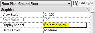
If you select across the whole model and filter out everything except lines, you can at least tell which ones are lines - but not which are model vs detail lines.  This is where the 'Display Model' property comes in handy:

Set it to 'Do Not Display' and all the model elements are hidden

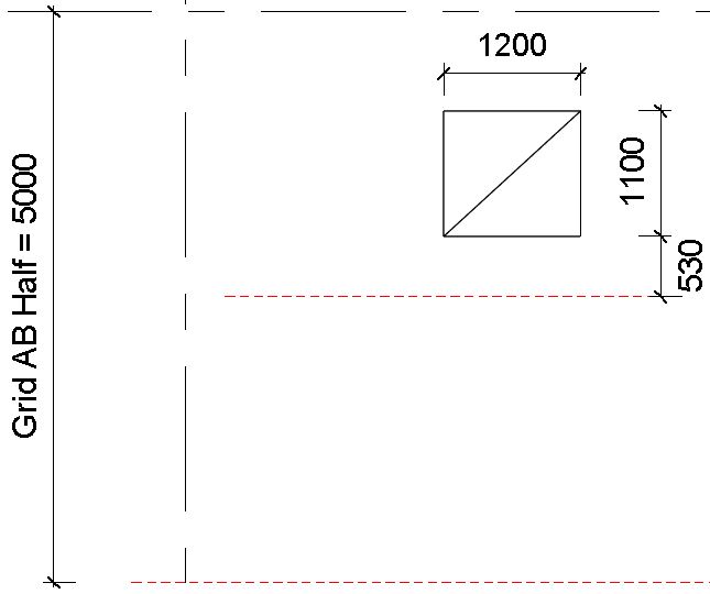
Interestingly, it keeps displaying grids & reference planes, which are neither model elements nor annotation - despite being lumped in with annotation on the Visibility Graphics dialog box.  They are in fact  what I call 'datum' categories.

One problem with this setting is that all the hosted annotation disappears too, so it is not easy to see things in context, nor can you be sure which hosted annotation is now hidden too.  This does have an added benefit of being able to check for 'dummy tags' (generic annotation symbols) and text that has been placed to look like real tags - all the real tags are hidden, and what is left visible is fake (or garbage as far as BIM is concerned).

There is a third option, which is extremely useful:  'Halftone'

This displays the model elements in halftone, and all the annotation as normal.  Now you can clearly see which lines are detail lines - they could be selected and converted to model lines, or better still, replaced by shaft openings.


As a 'Model Manager' you should be using this technique all the time to make sure that users are doing the right thing.  However, it is important to remember to set the Display setting back to normal when finished - better still, set it to normal in the view template and use the 'Enable Temporary View Properties' setting to do a temporary over-ride, which will reset itself when you finish.

Thursday, 3 September 2015

Weird Revit Stair Stuff - Stair Path Arrows in Detail Plan Views

Here is yet another inconsistency with the (not so) new Revit stair tools.

If you want to create a stair detail drawing, you might start off with a general arrangement plan that has a reference to a stair plan at say 1:20 or 1:50.  Good Revit methodology might suggest creating a callout from your general arrangement plan to generate the stair plan. .  If you do that, the default view type that it wants to create is a "Detail Plan View" - so most people would probably go with that option, without giving it another thought.  Bad move!

Here is where the inconsistency catches you out:  After spending hours setting up the stair sections and annotation on the stair plan, you realise that the stair path arrow is missing.  So you try to place a new one . . . .
Aaaargh!  It is greyed out - so you cannot place a new stair path arrow on your stair detail plan.  However, you can place stair numbers on a component stair in a detail plan view (but not on an old style sketch stair).

Why is this?

2.5D vs 3D 

I believe that it has to do with how a Revit "Detail View" is created:  unlike any other Revit plan view, it is a true 3D section through the model that is cut horizontally.  Other plan views are really only 2.5D because Revit uses all kinds of tricks and shortcuts to represent certain elements in a more traditional plan format rather than a literal slice through the element.  Stairs, railings and ramps are all special element types that have a system controlled 2.5D way of presenting in plan when cut. 
Other categories that might not show true 3D representations would be 'non-cuttable' categories such as furniture ad specialty equipment - they just show a top view.
On the other hand, categories like floors will show a true 3D representation when cut in plan - clearly demonstrated when you use a sloping floor instead of a ramp.
Detail View callout - literal 3D cut plan

Floor Plan callout - 2.5D plan representation

However, all of the above is no excuse for the software developers not to fix the issue so that you can put a stair path arrow in a detail view.

How to solve it?  Well you could just use a line-based detail component (with a built in arrowhead).  But your railings and stair cut lines won't look right either, so you start needing to add break lines, masking regions etc.

There is a better solution:

Plan view vs Detail View

In my opinion, you should just avoid using Detail View types for any plan details.  When placing a plan callout, you should always set the view type to Floor Plan - preferably to a pre-defined type that you have created for specific sorts of details.  Unfortunately Revit keeps reverting back to the Detail View type as its default.  If you forget to set this correctly when creating the callout, you are in trouble as it cannot be changed later.

There are many other reasons for doing this aside from fixing stair plans:
  • Detail views have significant limitations on where and when they can be referenced (see below).  Eg. On a ‘Detail Plan View’ you cannot reference a normal plan view;
  • You cannot change a detail view to a plan view (or vice verse);
  • Plan view callouts allow a different view range to the parent view; detail views have a far clipping offset, which is confusing and does not allow a different cut plane
  • In the Project Browser, Revit groups all Detail Views together (plans and sections), in quite a different place from normal plans - so if you use a mixture of Floor Plans and Detail Views for plan details it becomes a nightmare to organise and find the views.


Reference Other View

In V2016, rules for 'Reference Other View' for callouts are:

In a floor plan view, you can callout 'reference other view' to

  • Any drafting view
  • A detail view callout
  • A floor plan callout (but not a regular plan view)

In a Detail plan view, you can callout 'reference other view' to

  • Any drafting view
  • Any detail view callout
  • Not to any floor plan callout - (this is a big limitation)

In a drafting view, you can callout 'reference other view' to

  • Any drafting view
  • A detail view callout
  • A floor plan callout (but not a regular plan view)

For more info on these issues:

Friday, 18 April 2014

A Dozen Reasons Not to Use Adaptive Components in Revit

I love the idea of Adaptive Components in Revit - they have so much potential to allow us to break free of some of the traditional constraints of Revit.  But it is early days in their development - they have many of their own limitations.

However wonderful adaptive components are in Revit, they do have some downsides.  I have heard suggestions that we should all use adaptive components all the time instead of traditional Revit families.  Here are some reasons why you might not want to do that - and perhaps Autodesk can treat this as a checklist of things to address so that we can use them in more situations:

  1. Adaptive components do not have any 2D or 2½D capability - there is no Annotation tab in the adaptive family editor.
    - No text within Adaptive Components
    - No symbols
    - No symbolic lines
    - No detail components
    - No filled or masking regions within Adaptive Components
  2. You cannot add model text within Adaptive Components (except by nesting a traditional family with model text in it).
  3. Adaptive family file sizes can get extremely large, especially when you start nesting them or use repeaters. They don't seem to have the same capabilities of minimising file sizes that traditional families have when multiple instances of nesting occur.
  4. Visibility Settings are not obviously available in the UI within Adaptive Components (for controlling display levels and 2d view visibility) - [Edit. need to select an object and right-click to get to visibility]
  5. Controls are not available within Adaptive Components (for controlling flipping component orientation) - this is somewhat understandable as it could get complicated with multi-point adaptives;  nevertheless it is a limitation.
  6. If any one adaptive point is snapped to (hosted onto) an element that is subsequently deleted, the entire adaptive component also gets deleted, no questions asked.  Scary huh?  [Edit. I even found one situation where just duplicating the type of the host sent the adaptive component off into oblivion ! ]  This means that adaptive components behave more like true hosted families (doors, windows) that are completely dependant on hosts;  it would be much better if they behaved like face-based families that exist quite happily after their host face is deleted (refer to Chris Price's blog on Face Based Families).
  7. Placement of adaptive component points in the project do not lock to orthogonal - they do not use the Revit smart snapping capability, except for snapping to vertices and edges.
  8. Placement of "Site" category adaptive component points in the project do not snap/lock onto toposurfaces, unlike traditional site families.
  9. You can copy levels in adaptive families but they do not behave like two-level families (columns, generic) that have the levels baked into their templates, which then automatically lock to assigned levels in the project.
  10. Adaptive components cannot have a host element baked into the template – so it is not possible to include a void element in the adaptive component that will automatically cut the host face it is placed onto.  “Cut with voids when loaded” capability is very limited in categories it can be applied to – it cannot cut curtain panels, curtain systems, mass categories etc.
  11. As adaptive family templates do not contain any host elements, it limits the possibilities for using reporting parameters within formulas to adaptive points only - no wall thickness dependant frames etc.
  12. If you tag an adaptive component that has more than one adaptive point, the tag moves if any of the adaptive points move in the project - meaning that annotation on drawings will become even more unstable. 
  13. [Edit. Make this a "Baker's Dozen" as I forgot a really important one:  The list of categories available in adaptive components is seriously limited.  Most structural categories are missing!]
Adaptive Categories

This is not a list of reasons to never use adaptive components.  It is more a checklist to warn you of some limitations , so that you can plan when best to use them.  The list is not comprehensive - for example, it does not address issues of hosting, and analysis that might be vital for MEP or structural families. This list does not address the operational differences or difficulties within the adaptive family environment - for more detail on this, refer to Rival Revit Environments.

Don't plan to replace your traditional Revit library with an adaptive version just yet.
But there are Reasons to be cheerful about adaptive components.

Monday, 10 March 2014

Revit Stair & Railing Selection


The new Revit 2013 Stair and Railing tools brought with them some tricky changes to the selection process that might catch you out.

Selection filters now have some new subcategories for stair components, stair annotation and railing components. All the new stair subcategories have been prefixed with the word “Stairs:”, which makes them easier to find in a list; new stair tags are likewise prefixed with "Stair". Sadly this logic was not applied to new railing subcategories: Top Rails, Handrails and Supports do not have a Railing prefix in the filter, so they don't show in the list in a sensible order.  In fact it can get quite confusing because we now have "Stairs: Supports" and "Supports", which are two entirely different things so you have to remember that the latter is for railings only.
When you look at a typical selection filter list the railing subcategories are jumbled up with the rest - this becomes important when you need to specifically exclude some of the subcategories from your selection (see further on).


The same naming convention is used in the properties dialog box.  At least it is consistent, if annoyingly wrong!

Railing Terminations and Extensions cannot be selected, nor do they list with separate subcategories - they are only accessible through the type properties of Top Rails and Handrails.

Visibility / Selection

Any of these railing or stair components can be Tab-Selected or selected by dragging across them.

The rules for selection/display of Railing Supports are mysterious and confusing:
  • In section and 3D views they are visible at all detail levels.
  • In plan views they are only visible in Fine detail level;
  • Railing Supports below the cut plane in plan views are visible (fine detail level only), and can be selected by dragging or tab-select;
  • Supports above the cut plane are only visible during pre-selection or selection highlight (fine detail level only);  they cannot be selected by any method except changing the view range cut-plane or going to another view on the next level up;
  • In Medium or Coarse detail level below the cut plane in plan view, they can be selected by dragging, in which case they display a pin only (no graphics);
  • In Medium or Coarse detail level below the cut plane plan view, they can be tab-selected (location by guesswork), in which case they do not display a pin but do show a highlight line at their origin (no graphics);
Medium or Coarse Detail Level

Fine Detail Level- railing supports visible

Hidden supports visible when railing is selected

 
It is important to note that railing supports can be selected even when not visible in plan - but only below the cut plane in medium or coarse level of detail.
Invisible Supports selected

Pinned Elements

If you select by dragging across a stair, you may get pins showing up on the stairs. These are actually for the Top Rails, Handrails or Supports, which are now separate sub-components (somewhat like curtain wall components) - this means that you can often get numerous confusing pins showing up on screen. This applies to new style railings on both old or new type stairs, but not old style railings.
You can also Tab-Select these railing sub-components individually.  Again, they display pins, but each behaves slightly differently (and differently to curtain wall sub-elements).

Once you have successfully selected a railing sub-component the displayed pin behaves slightly differently for each category, as described below.

Pinned Element Properties

You can unpin them to unlock and change some of the instance properties:
  • Type selector becomes available for all railing sub-categories when unpinned - so you can change the type (Type Selector grayed out when pinned)
  • Unpinned railing supports allow the "Hand Clearance" instance property to be changed
  • Type properties can be accessed and modified without unpinning them (any sub-category)
Pinned Railing Support

Unpinned Railing Support

Stair Component Properties

Stair components do not have pins, but some of their properties can be changed without editing the stairs.
  • Runs and landings allow height property changes - this will have knock on effects to adjacent components - refer to Modifying Landings
  • Stair supports may allow changes to cut properties of free ends

Sub-Category Selection Limitations

Depending on how you select elements (multiple selection by dragging across screen or tab-selecting), you will encounter some inconsistent limitations to what you can do with selected stair components or railing sub-categories:

  • Move Command (Multiple Selection).
    • If you have any pinned Railing Supports explicitly included in your selection of elements (ie, in selection filter list), it will not allow you to move the whole selection.  Therefore you have to remove the supports from your filter selection list before moving the selection.  This will surely catch out anyone but a railing expert.
    • This does not apply to Top Rails, Handrails or any stair components - whole selection can be moved even when they are explicitly shown in the selection list and pinned.
  • Move Command (Individual Selection).
    • If you individually select any stair components, they cannot be moved without first editing the stair - in fact the Move command is greyed out;
    • If you select a (railing) support, you can move it after unpinning it - within reason (beware of how much it moves - it measures up the diagonal even if you give a horizontal distance);
    • If you select a handrail or top rail, it cannot be moved even if unpinned - but it lets you try!
     
  • Delete Command (Individual Selection) 
    • Stair components cannot be deleted without editing the stair
    • Railing Supports, Top Rails and Handrails can only be deleted after unpinning them
    • Deleted Railing Supports can be reinstated by selecting the host Handrail and clicking Reset Rail, but it will reset all changes to supports on that handrail
    • Deleted Top Rails and Handrails can be reinstated by resetting the host Railing

  • Edit Rail Command 
    • Unpinning a Handrail or Top Rail seems to make no difference to allowing it to be edited - can be edited when pinned
    • However, if a pinned Rail is edited, it will flag the Handrail or Top Rail as unpinned
    • Repinning a Handrail or Top Rail will remove all edits and reset it to original state - beware, as it is easy to lose work, as you might think that the pin command will lock all your changes!
    • Likewise, repinning a Railing Support will restore it to its original location

     
  • Groups
    • If any stair or railing sub-component is explicitly selected, but its host is not selected, then the Create Group command will be greyed out and unavailable
    • In which case, you need only add the host element (stair or railing) to the selection to enable the Create Group command
    • If a railing is added to a group, all its hosted elements will go with it
    • If a stair is added to a group, its components will go with it (run, landing, support), but its railings will not be added (unless explicitly selected)
     
  • Design Options
  • The rules for adding selections to design options are subtlely  different from creating groups:
     
    • If Top Rails, Handrails or Railing Supports are explicitly selected along with their host railing they can be added to a design option
    • If Top Rails, Handrails or Railing Supports are explicitly selected without their host railing they cannot be added to a design option
    • The same rules apply to stair components
    • If a railing is added to a Design Option, all its hosted elements will go with it even if they are not explicitly selected
    • If a stair is added to a Design Option, all its hosted elements will go with it, including its railings, even if they are not explicitly selected.  This is different behaviour to creating groups