BILT Speaker

BILT Speaker
RevitCat - Revit Consultant
Showing posts with label material. Show all posts

Sunday, 15 August 2021

Display Priorities of Solid Fill in Revit Materials

Back in Revit 2012 Autodesk changed the way materials work - so that they had separate graphics and appearance properties.  This was the start of much confusion for many users - and still to this day it catches people out.  You know the drill:  duplicate a material;  change its appearance properties and suddenly a hundred other materials change too . . . .

Well, I am not going to address that issue directly.  Instead I want to look at a more subtle confusion that some users encounter:  Exactly how do the different material properties display in each 'Visual Style' - it will not always be what you might expect or consider to be logical

Material Properties

In order to analyse this issue we start with two very simple material definition examples, applied to two elements in a Revit project:

Material 1 - Demo Generic

  • Light grey shading 
  • Light Blue appearance (different colour to shading)
  • no surface patterns


Material 2 - Demo Green

  • Light green shading and appearance;  
  • no surface patterns


Visual Styles

These materials display as expected in the various 'Visual Styles' in Revit - because we know that the graphic 'Shading' colour property matches the 'Appearance' colour property in material #2 but not in #1 

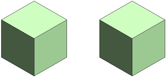
Material #1 on left,              Material #2 on right

Hidden Line Visual Style

Shaded Visual Style

Consistent Colours Visual Style

The colour displayed for material #1 (left) in Realistic and Ray Trace visual styles is different to shaded and consistent colours because the material properties do not match - this is to be expected.

Realistic Visual Style

Ray trace Visual Style

Material #1 on left,              Material #2 on right


Lighting

These views are lit with default sun and lighting settings (ie. light source over the right shoulder of the viewer)


Use Render Appearance

One thing that users often forget to address is consistency between the 'Graphics' and 'Appearance' colours.  If the colours are dramatically different, then materials look completely wrong, particularly in 'Shaded' views.

There is a quick and easy way to deal with this - it is the 'Use Render Appearance' checkbox to make sure the shaded colour matches the appearance colour.


This property can be used as a one-off operation - ie, tick the box to change the colour, then untick it.

Or you can just leave it ticked if you want the shading to update when the appearance property might change in the future.

  • NB.  Make sure that the appearance colour is correct first - as there is no 'Undo' so you might lose a shading colour definition.
  • Do not use this method if the shading colour is correct but appearance wrong


Surface Patterns in Materials

When you add surface patterns to materials is where things get more complicated . . .

We will make two more materials, based on the light green shaded material - these will use the same light green 'Appearance' (unchanged).

Material 3 - Demo Green Line Hatching

  • Light green shading 
  • Light green appearance;  
  • Line Cross-Hatching foreground surface pattern

Material 4 - Demo Green Solid Hatching

  • Light green shading 
  • Light green appearance;  
  • Line Solid Fill foreground surface pattern

Visual Styles

Hidden Line

  • Cross-hatch pattern is displayed as you might expect
  • Solid fill displays with solid colour - but without any lighting effects
Material #3 on left,              Material #4 on right

Hidden Line Visual Style

Shaded

  • Cross-hatch pattern is displayed on top of the shading colour
  • Solid fill displays replaces the shading colour - it is completely obscuredthis can be confusing if the user has not studied the material properties carefully
Shaded Visual Style

Consistent Colours Visual Style

Realistic (and Ray Trace)

  • Cross-hatch pattern are not displayed at all - unless a hatching pattern is defined within the material appearance (not a simple thing to achieve)
  • Appearance Colour replaces the Solid fill colour this is the reverse of what happens in a Shaded visual style - so it can be confusing
Realistic Visual Style


Background Hatching

Just for the record, here is what happens with background hatching - it follows the same rules as Foreground hatching.  [NB. This capability was added in Revit v2019]

Material 5 - Demo Green Line Background Hatching

  • Light green shading 
  • Light green appearance;  
  • No foreground hatching surface pattern
  • Line Cross-Hatching background surface pattern

Material 6 - Demo Green Line Foreground & Solid Background Hatching

  • Light green shading 
  • Light green appearance;  
  • Line Cross-Hatching foreground hatching surface pattern
  • Solid Fill background surface pattern

Visual Styles Materials 5 & 6

Material #5 on left,              Material #6 on right

Hidden Line

Shaded

Consistent Colours

Realistic


Conclusion

Solid Fill surface patterns are the one part of this Visual Style issue that cause display inconsistencies.

You may have good reasons for using Solid Fill surface patterns as part of a material definition - in which case go for it.  Otherwise, they are to be used with caution in normal Revit use.

Another approach to avoid the inconsistencies would be to make sure the appearance, shading and solid fill colours all match up.


Don't forget to check how many materials are sharing the Appearance asset before you change it - it is the number above the hand on the Appearance tab.


Friday, 22 January 2021

Revit Stair Wall Joins in Section

Following on from an earlier post about joining stairs and floors, I just wanted to clarify what happens when you try to join Stairs and Walls in section . . . .

We saw previously that Revit does have some limited capability to join stairs and floors at the base of a stair - but it has many limitations.

Joining a Wall and a Floor

All good Revit users would know that if a floor and a wall are of the same material, and they have coincident or overlapping edges, they can be "joined" in the model.  This is not just a graphic tool that is done per view - it affects the model in potentially all views, including material quantity schedules.  If an overlapping wall and floor are joined, the volume of material that was previously counted twice is corrected after the join so it is counted once.

Join Geometry


Select floor and wall to join
Providing that the elements are of the same material, the line between the floor and wall disappears.  In this example, the 'Level' line is revealed, as it happens to align with the top of the floor.

Joining a Wall and a Stair Landing


Try the same thing with a wall and a stair landing . . .


What happens?  Absolutely nothing.  After selecting the wall, Revit will not even highlight the stair landing (or vice versa if you select the landing first).

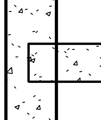
Well, that is just plain ridiculous!  You might argue that the wall and landing would be cast separately on site, so there should always be a joint line between them - but the graphic convention is to not show a line, or at least show a thinner line between them in section.


What to Do?

There is no good workaround to this problem - each method is clunky and not robust.

Linework Tool


Linework Tool

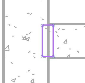
If you try the linework took, you immediately discover that it will not do the job for you, as it affects the whole wall.


That isn't very helpful, as you only want a small segment of the wall edge line to be invisible (or thin line).

Another strange Revit quirk with the linework tool is that when you select a line in elevation (or projection in plan) it gives you blue dots at each end , which can be dragged so that only part of the line has its style overridden.  That is a very useful capability - but infuriatingly, it does not work on cut lines.


Yet another quirk is that the underside of a run is treated as one line when cut (section), but in elevation, each step is a separate line segment.  Why, or why?

Filled Region

Filled Region
A common method of hiding a multitude-of-sins in Revit is to use Filled Regions.  These have pros and cons:

  • They are quick and easy to understand for most users
  • Their edge lines can be of different styles, including "invisible" as part of the sketch - so they hide model lines underneath 


  • They will merge with underlying element hatching , providing the material hatch style matches the filled region hatching


  • They are view-based, so any patching up on one view will not show on other views
  • Line edges/junctions can be messy when viewd close-up

  • If the model is changed, the filled region will not change with it (unless you constrain the sketch lines, which is not generally advisable - as your model very quickly becomes over-constrained and unworkable)

Cut Profile

Cut Profile (View Menu)
You could try the 'Cut Profile' command - this allows you to modify how an element looks in a particular view.  Once initiated, it takes you into sketch mode - so you can draw a shape to add to an element (or cut from it).

The end result is not very promising in this situation

  • The added shape does not obscure the wall line in the way that a filled region does
  • The sketch lines cannot have a line style (unlike Filled Regions)


The worst thing about this idea is that the Linework tool does not work at all on cut-profile shapes - thus making this tool almost useless!

Conclusion

Sadly there is no clever workaround.  The conclusion is that it is not worth fighting Revit on this one - just accept the joint line between wall and landing.  In many cases it is not an issue, but when the stair and wall are both cast in place concrete, it is very annoying.

Monday, 3 February 2020

Room Bounding Structural Column Materials in Revit


I recently discovered yet another obscure, hidden away setting in Revit - when I was investigating the "Room Bounding" property of different elements.

It seems that some structural columns have a "Room Bounding" property - but not all.
This has to be one of the weirdest, arbitrary decisions made by the Revit programmers:

Material for Model Behaviour

Structural columns have a weird property - so obscure and arcane, not to mention hidden away.
'Material for Model Behavior'

This property that can only be set in the Family Editor – in ‘Family Category and Parameters’: ‘Material for Model Behaviour’.


It can be one of 5 settings, each of which enables different properties and behaviour in the model:
  • Steel
  • Concrete
  • Precast Concrete
  • Wood
  • Other
Depending on which one you choose, it will enable properties in the family.
  • Steel has Connection properties
  • Concrete & Other have Rebar properties
 

These settings are hidden away behind the 'Family Category and Parameters' settings - in the project there is no way to tell which setting the family has, apart from the specific properties displayed.

You would have thought that this only affects structural engineers?

But wait.  It affects architects too . . . . .
  • Concrete has ‘Room Bounding’ properties (it is the only one that does)


Why, oh why are wood and precast concrete not room-bounding?  There are a huge number of timber structures around the world that provide perfectly good enclosures.
Wouldn't it just have been easier to make all columns potentially enclose rooms, instead of hard-coding someone's bizarre ideas about how a building might work?

Room-Bounding

When working in a project, and you discover that a 'Room' is not enclosed when you expect it to be, this is one of many things to check.
There are some other quirky Room-Bounding behaviours in Revit, to be detailed later  . . .