BILT Speaker

BILT Speaker
RevitCat - Revit Consultant
Showing posts with label show. Show all posts

Monday, 25 May 2020

Weird Callout Behaviour in Revit

A few months back I wrote about some of the weird rules for Revit Callouts when you use the 'Reference Other View' option.

There are some strange and frustrating restrictions, which mean you need to plan carefully about what view types/families to use for callouts, and in fact for any views.

There are also some weird restrictions in how Callouts work when you don't use 'Reference Other View' - I refer to those as "Real Callouts".  I am going to record those here.

Stop and Think - Which Parent View?

Before placing any "Real Callouts",  stop and think about which view you want to place the callout on - you should already have a good plan for how your drawing set referencing is going to work.

The reason for this is that once you place a Real Callout on a view, it does two things:
  • It creates a new view that is automatically cropped to the extents of the callout that you just created.
  • It places the callout element on your view - typically a dashed line rectangle with a circular reference bubble.
It is  really important to know that once you place a Real Callout on a particular view, it can never be moved to another parent view.

The only workarounds are:
  • Start from scratch - delete the callout + view, which means losing all your annotation and any other reference callouts to that view.
  • Hide the callout on the parent view, and make a Reference Callout on another parent view.  This means that the old parent view can never be deleted - you would lose the callout view (refer to Deleting Callouts below). 
    This is a last resort workaround that I would not recommend.

Callout View Families

Detail Views vs Plan Views

The first issue to watch out for when creating Real Callouts is which view type you select (or don't select if you just accept the default).  For plan callouts you have two family options (and then choices of any view types that you have created):
  • Detail Views
  • Floor Plan Views

The really important thing to know here is that once you have made a decision between Detail or Floor Plan family, you can never change your mind - the families are not interchangeable.

View types are changeable - so you can change a callout from one plan view type to another plan view (but not to a Detail view).

Once you have chosen a callout view family/type, there are many weird and inconsistent rules about which view families can be referenced to and from callouts - refer to weird rules for Revit Callouts for 'Reference Other View'

For those and other reasons, I normally try to avoid using Detail views at all in Revit - see more reasons below, and refer to Weird Stair Path Stuff.

Detail Views vs Section Views

When creating Section view Callouts you also have two family options (and then choices of any view types that you have created):
  • Detail Views
  • Section Views
Unlike plan details, section details can be changed to normal section views - this is inconsistent, although it is welcome not to have that restriction.


Weird Detail View Behaviour

Detail views behave quite differently to other view types:
  • Plan and Section views are typically grouped together in the project browser - it does not distinguish between them.  This can be confusing when searching for views.
  • Detail views can be rotated in section (or elevation) from a vertical (section) orientation to a plan orientation.  If you know what you are doing you can use this to your advantage - but is not advised for inexperienced users.  It will most likely cause much confusion.
  • When creating Real Callouts from a Detail view, they can only be another detail view.
  • Stairs and railings are displayed as cut 3D models (wherever the view cutting plane is), rather than the Revit conventional 2D representation on other plan views - refer to True 3D Stair View in RCP.
  • Symbols nested into families (such as electical fittings - switches, power outlets) are not visible in Detail views.
  • Section and Plan Detail Callouts have the ability to set the depth of view the same as the parent view or independently - however, the controls are by 'Far Clip Offset' for both section and plan, not by view range.


Plan Detail Views

Plan Detail views have special rules (different to Section Details):
For Plan Detail views, the callouts are generally only visible in the views they are placed on, with one exception:
  • There is a ‘Show In’ property that can override this behaviour
  • Plan callout views are normally set to Show In ‘Parent View Only’ 
  • If this is changed to ‘Intersecting Views’ then the callout can potentially be visible in other plans within the same view range (thus behaving more like section detail callouts) - be warned, this will confuse the heck out of most Revit users.

  • Be aware that ‘Intersecting Views’ detail plan callouts can also be visible in sections – they may appear as a line or with a reference head depending on the properties of the plan view


Section Detail Views

Section Detail callout views are potentially visible in section views other than their parent view.  They behave as if they have a hard-coded 'Show in Intersecting Views' property.  They might be visible under the following conditions:
  • The callout view crop boundary is wholly within the crop boundary of the other section view
  • The callout view section line is within the Clipping Distance of the other section view
  • There are no other scale-related, category visibility or filters hiding them. 

Duplicating Views

  • If you copy and paste a real callout, it actually creates a new view (and new callout).  In most cases this is not especially useful, as you are more likely to want the same reference to the original callout view - in which case it would need to be a 'Reference Other View' callout.
  • If you copy a parent view by ‘Duplicate with Detailing’ it creates a new view for each callout – each would have a different reference on the duplicatd parent view. 


Deleting Views

  • If you delete a parent view (plan or section), it will automatically delete any callouts placed on that view, and the callout views - although it does prompt you with a warning that it will delete those views.
  • There is no way around this because once a callout is placed on a particular view, it cannot be moved to another parent view.
  • This is a major drawback to using callouts in Revit.

Next Time . . .

In addition to the issues above, there is a limitation on not being able to have a callout rectangle that is slightly larger than the crop region of the callout view - thus making your drawings messy and hard to read.  Refer to Callout crop boundary mismatch


In the next blog post on this subject I will suggest an alternative working method that avoids some of these pitfalls and inconsistencies.


If you can remember all these rules and exceptions, congratulations!  Try remembering them again in a few months time.

Friday, 23 October 2015

Weird Stair Stuff - part 6 - Showing Concrete Stairs Under Tread Finishes

I was recently asked if it was possible to show a concrete setout plans (and sections) for a monolithic Revit stair that has a tiled finish or timber treads on top of the concrete - ie. to hide the finish and show the concrete riser lines only (which are in a different plan location to the finishes risers shown on the architectural plan).  You would think it should be an easy task given that most structural engineers would want to see only the concrete part of a stair.  Wrong!

By default, in an architectural plan view, Revit displays the finished nosing lines and the hidden riser lines (which may be coincident in plan if you do not have a projecting nosing).  One of the reasons for this is that Revit is not displaying the 3D model in plan views - it displays a hybrid 2.5D version that represents the stair in plan according to Revit's mysterious rules and system controlled subcategories (which are quite frankly, very limiting).
Normal architectural plan view of stair
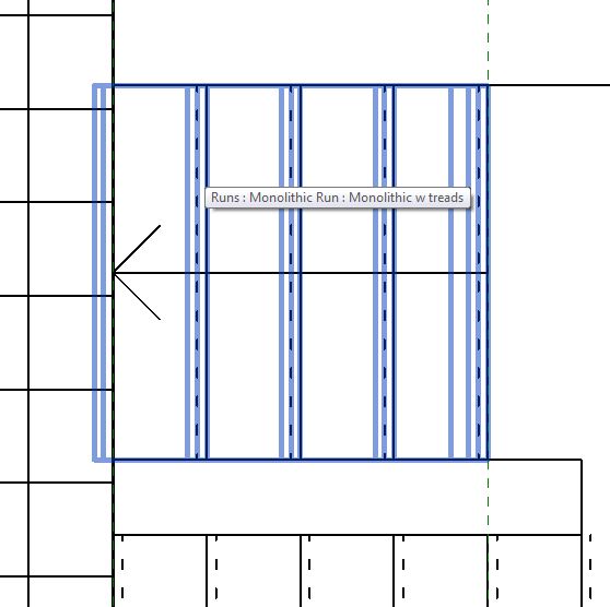
Changing the Discipline of the view to structural, makes no difference to stairs.  Hiding various stair subcategories will not show the hidden concrete underneath, whatever you try.  If you hover the mouse over the run (and tab to get just a run), it highlights the actual 3D model with all the hidden lines available - but they disappear as soon as you select it - how tantalising!
Pre-select run shows hidden lines of concrete below

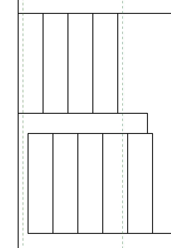
If you hide the floor finish at the top of the stair (in this example it is modelled as a separate floor) you can see that there appears to be a gap - this is because Revit stops drawing the plan where it expects the top nosing line to be rather than where the top riser is (even though it does not model the nosing if your stair 'Ends with Riser').
Gap at top of stairs when floor finish is hidden

Back in the section view, if you turn off the 'Treads/Risers' subcategory it leaves just the concrete substructure.

Notice that the concrete actually extends to the back of the riser in section (and 3D) but this is not shown in plan.  The section also has a couple of other issues:
  • The concrete at the top of the stair stops in line with the back of the top riser, where in fact it should extend up until it meets the underside of the floor slab.  Obviously the stair has no knowledge of where that slab is or how thick it is, but there should be a way to deal with this.  There is a Run property for 'Extend Below Slab' so why not have one at the top.
  • There appears to be a joint between the landing and the upper run even though they are the same material - in fact it is a step in the landing because the concrete landing edge aligns with the nosing rather than the concrete riser.  This would need to be manually adjusted if you want them to align or if you want a finish applied to the landing edge.
Concrete Section - treads/Risers hidden
This is getting close to what a structural engineer might want to see, or for an architectural concrete setout drawing.  So how do we get this to display the same information in plan, when Revit really does not want to do so?

As a workaround, we could try using one of Revit's really weird features, as described in my post about stair arrows and detail views:

Detail view callout

Create a detail view callout of the stair.

This type of view (Detail plan view) is actually a true 3D view (a horizontal section), which does not use the normal Revit 2.5D representation of stairs (and ramps).  The stair shows the top riser line (including thickness) and the actual nosing locations where modelled.  In the snapshot below the floor finish is hidden so you can see the top riser.
Stair in Detail plan view type

So now it follows the subcategory rules that normally apply to a section:
  • Nosing Lines, Riser Lines and Outlines are not relevant to this view type
  • Treads/Risers subcategory does apply - try changing the colour override to test it
Treads and risers overridden in detail plan view

Now try turning off the visibility of the Treads/Risers subcategory - and magically you can see the concrete underneath, because that is controlled by the overall 'Stair' category.

Of course there are some downsides to this method of creating concrete setout plans - Detail plan views are not normal Revit views:
  • You cannot place stair path arrows on detail views (although you can place stair numbers)
  • You cannot 'Reference Other View' callouts to regular plan views - so you would have to work out your view referencing carefully.
  • Detail views do not have a 'View Range', so you have to rely on the parent view or 'Far Clipping'
  • View cut plane is controlled by parent view - and cannot be overridden
  • You cannot use Plan Regions
  • If someone deletes your parent plan view, Vamoose detail view.
  • the list goes on . . . . .


Refer to  True 3D RCP View of a Stair in Revit for more uses of this technique
Refer to stair arrows and detail views for more detail on the downsides of this technique
Go to Revit Stair & Railings Index Page

Tuesday, 26 May 2015

Got Your Repeaters in a Twist?


How many times have you tried to create a 'Repeater' from multi-point adaptive components in Revit, only for the result to be a tangled mess, instead of the neat array that you were expecting? 

You may be in luck - there could be a simple solution. . . .

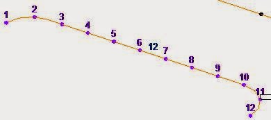
When you select the underlying 'Divided Path' that the repeater is hosted on, it will display the number of nodes (a blue number above the centre of the divided path)
It also shows up in the properties dialog box.  A few other useful properties are also there, including 'Show Node Numbers', which is off by default.  Try ticking the checkbox.
 It will display each node number as well as the total
If you select the other divided path, and do the same thing, you may find that the node numbers go in the opposite direction.  Unfortunately you cannot display both sets of numbers at the same time - so you need to select them individually and remember the direction
If the numbers are in opposite directions, all you need to do is reverse one of them by clicking in the 'Flip Direction' checkbox.
You might be lucky and have the repeater magically untangle itself, but that is unlikely.  More likely it will still be wrong - maybe some missing elements if the node numbers are slightly out of synch.  It is probably better to undo the repeat command before you flip the direction.

Sometimes the hosted adaptive component will disappear when you flip the direction - in which case undo and delete it first - as Revit still thinks it is out there somewhere.

If you have just one hosted adaptive component, you may find that it just gets stretched to another location when the direction is flipped.
In which case you could select the adaptive point at one end, and rehost it to the correct node on the divided path
Once the nodes are matched up you can try the Repeat command again

If that didn't solve the problem, it could be more complicated!  Have a look at some of my other posts on Repeaters - listed on the Repeater Index Page