
Offset Properties
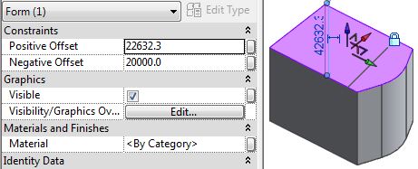
Locked extrusions have 'Positive & Negative Offset' properties, that drive the distance of the end facets from the original profile. These behave in different ways depending on exactly how the extrusion was created and locked.Reference Line Extrusions
- Create Form using reference lines as the profile
- Creates an extrusion, which is automatically locked
- The form has Positive and Negative Offsets, relative to the reference lines

- Select the base facet, drag down

- Negative offset value
- Reference lines remain in original position

- Unlock the extrusion - no offset properties

Model Line Extrusion
- Create Form using model lines as the profile
- Extrusion is not locked automatically
- Does not have offsets

- Select the top facet
- Lock the form to an extrusion
- Padlock does not appear (unless you reselect the form)
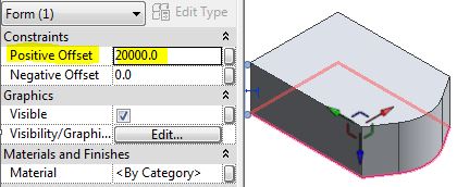
- It now has Offsets, relative to top facet (not the base, which was the original profile)

- Drag the top facet up and it shows a positive offset
- The Negative Offset is the position of the bottom facet relative to the original position of the top when it was locked - there is no visible record of that location.
- Undo
- Edit profile
- It does not ask you which profile to edit (as it is locked)
- Revit goes into Sketch edit of the top facet (not the base, which was the original profile)

- Cancel
- If you were to 'Dissolve' the form at this stage, you would end up with only the top facet, which is in a different location to the original profile.
- Do not proceed with 'Dissolve'; or Undo, if you did.
- Unlock the extrusion form (the Offset properties disappear)
- This time, select the bottom facet (or a line/edge on it)

- Lock Form
- Offsets now relate to bottom facet - more logical in this situation
- Edit Profile
- Sketch edit is now the bottom facet (original model line profile)

The moral of this tale is that you need to plan very carefully when creating extrusions - first choose whether to use model or reference lines; If you chose model lines (which allow easy editing of the profile to add/remove segments) then choose a line/edge carefully before locking the profiles.
Conclusion
A real life example of when this would be important is the creation of a 'context' model for your site:You want to model adjacent buildings as simple extrusions, and you want to control their height by typing in known RLs, without having to calculate heights.
- As you probably want to work in context in a project, you might create an in-place mass family;
- However, it could also be done in an external family, as a generic Adaptive Component (with no adaptive points), changed to a site category;
- Draw the profiles on a Datum level (or reference plane) at RL zero (or round number, say 100 or 1000 metres)
- Choose model lines for easy profile editing (or reference lines for stability);
- Create Form
- Deselect the top facet
- Select a line on the base
- Lock Profiles
- Select the top facet
- Type in the RL (in mm) for the building height

- You could also adjust the base facet height using a minus value in the negative Offset property to represent the RL of the base of the building

No comments:
Post a Comment