BILT Speaker

BILT Speaker
RevitCat - Revit Consultant
Showing posts with label transition. Show all posts

Saturday, 26 January 2019

How Do You Solve a Problem Like Ma Railings?


Have you ever encountered a problem with out-of-control railings in Revit?  OK, so maybe the structure shown above is not a haywire railing, and was meant to be like that, but most Revit users have struggled with trying to model railings as they should be.

How Do You Solve a Problem Like Ma Railings (in Revit)?  *


* with apologies to Richard Rodgers for misappropriating his song title (How Do You Solve a Problem Like Maria? from the Sound of Music, By Rodgers and Hammerstein) - not to be confused with Richard Rogers (no d), the architect who designed many famous buildings, such as the Pompidou Centre in Paris (with Renzo Piano) and the Lloyds Building in London.

Richard Rogers surely did not struggle with trying to model railings in Revit, as those buildings were designed long before the advent of such software.  These days we certainly do struggle with the software - Revit has been around for almost 20 years and it still it does not enable us to model Railings the way we want them (except for the most simple handrail).  There are many problems with the railing tool in Revit, some of which have been documented on this blog - see the list below.  Over the years, we have benefitted from several minor improvements to the railing tool - for which we are very grateful.  However, there is one fundamental problem that has not been resolved - and that is the inability to control the location of individual balusters.

Baluster Placement - a Fundamental Flaw

The railing sample file shows some relatively complex looking examples - but these are just straight runs on the level.  As soon as you try to use them on stairs, things start going wrong with the baluster placement.

This example is done using two alternating balusters - one is just a post, while the other is glass with fixings.  The glass baluster is very good at adjusting the angle of its top and base (if you create the family properly). 
 
When it comes to spacing, it is pretty hopeless:  you get gaps whenever there is a break in the pattern.
Standard railing with glass balusters
There are some limited controls within the baluster placement type properties, but no single combination of settings will ever work on the whole stair railing.

Spreading the pattern to fit does resolve some issues, sometimes. . . .

Changing the 'Break-Pattern' property to 'Never' can have some weird results

Reverting the pattern to 'Centred' does not fix it either - you may end up with panels across a change in angle, where the panel is not trimmed properly.

Workarounds

There are a number of ways that people get around these problems, but none of them is satisfactory:

1.  You can try using 'Handrail Supports' to represent balusters, but that has at least two problems:
  • Handrail supports do not respond to changes in angle of the stair, so you need to build that in as a user control that has to be manually set every time
  • Handrail supports can be unpinned and then moved (or changed to another type), but the moving process is very tricky - see Moving Handrail Supports
    It is also possible to very easily lose the positions by accidentally resetting the railing.
2.  Model the glass as a continuous rail element, use balusters and/or handrail supports to represent the fixings and vertical joints in the glass.  More on that another time.

3.  Model the railing 'in-place'.  This is a really bad idea as it screws up the subcategories, visibility etc;  And worse still, it does not update when the stair changes

4.  Just model a Top Rail / Handrail (with no balusters), which shows up in plan.  Document the railing in 2D as drafting views or as detail elements on stair sections.  This is a terrible solution (very un-Revit-like), but it can save huge amounts of modelling time - so it is done quite commonly in the industry.  Of course, it can lead to errors on site . . . .

Railing Fixes

If we had the ability to control the baluster placement in much the same way that curtain walls operate, it would help resolve this fundamental flaw in the railing tool;  this would require the ability to include variable width panels too.  Of course there need to be many other minor fixes in addition to that. 

On the Autodesk Revit Roadmap, Railings were flagged as 'fixed', a couple of years ago, on the basis of a number of minor enhancements.  Clearly it is nowhere near being fixed - see this request on 'Revit Ideas'  Railing Overhaul - Resolution of Limitations - from Chris Price (Mr Spot).

Weird Railing Stuff Blogs

Over the last few years I have posted many blog articles on the many weird quirks of using Revit to model Railings.  Some articles just document the inconsistencies and strange behaviour - just so you know what is going on; other articles offer some workarounds and ground-rules that might help you along:

Revit Railing Enhancement Requests

Autodesk  have a 'Revit Ideas' website that allows you to vote for enhancement requests.  I have compiled a list of stair/railing related ideas - please, all of you vote for some of these requests - if you don't vote, Autodesk will continue to consider them as fixed.

Friday, 4 September 2015

Perfect Stair Railing Transitions at Half Landings

I am currently in Sri Lanka en route to the inaugural Asian Revit Technology Conference in Singapore - RTC Asia 2015 at the Singapore  from 10 - 12 September 2015.  If you can possibly get to RTC in Singapore next week you really should do so - you will certainly learn a lot about Revit and/or BIM, regardless of your skill levels.  Your investment in the conference will pay for itself many times over.

The reason for my current detour is to do some research for the conference - to learn from one of the great masters of architectural detailing, renowned Sri Lankan architect Geoffrey Bawa.  He has designed many beautiful buildings by perfectly managing spaces, repeating patterns and a great attention to detail - all with an elegant simplicity.


At the conference I will be presenting a lab session on stairs and railings (afternoon on day one), so I have been paying close attention to handrail details.  Some of Bawa's details are very chunky, as per the style of the time - but they still look good several decades later.


Sometimes Bawa's details are less elegant than whimsical - in fact can be downright scary, but those examples are few and far between: 
5-headed cobra handrail termination
Now that would be a challenge for Revit to model as a handrail termination!

Railing Transitions

Handrail transitions at half landings have always been a problem for Revit to achieve neatly, but with the changes to railings in v2013 the situation actually got worse - if you try to use the new Top Rail or Handrail features.  Revit seems to require lots of extra horizontal space to make the turns - as documented previously - Top Rail Transitions and Top Rail Offsets. 

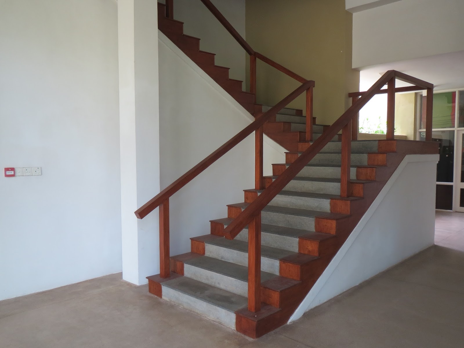
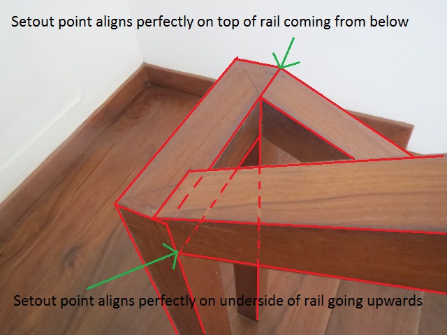
Geoffrey Bawa detailed his handrails to transition perfectly where they turned a corner without the extra horizontal lengths that Revit insists on, as seen below:


Revit Transitions
Bawa Transitions


If Bawa and his craftsmen could do it perfectly, why can't Revit?  Revit should learn from a great master.


Saturday, 20 September 2014

Weird Revit Railing Stuff - Part 3 - Rail Offsets


Rail Offsets

Following on from my earlier post (Top Rail Transitions) about the subtle differences between old and new style railings, here is another weird difference.  In my attempts to get the transitions working properly on the inside railing, I played around with the railing offsets in plan at the stair half landing.  Each railing type gave different result - rather than try to explain what is happening, here are the offsets and outcomes for each type in the situation where the risers on a half landing are staggered by one tread (which should be buildable).

Old Style Railing (no top rails)

When the railing sketch exactly follows the edges of the stairs and landing, none of the types work, as we have seen previously.  


So, with the old style railing (no top rail), I first offset the sketch line on the landing by 16mm.
 This was enough to get the transition to the upper run railing section working, but not the lower run.
16mm offset landing sketch line
Section view - 16mm offset landing sketch line
 So then I tried increasing the sketch by 1mm to 17mm, which fixed the lower transition too

 Sadly the mitred joints show in 3D views
17mm offset landing sketch line
Section view - 17mm offset landing sketch line

From the section it can be seen that the transition only works because the 17mm allows the underside of the sloping rail to get to the correct height before the 50mm width of the rail turns the corner (different size rails and different stair angles would need different offset dimensions).

NB. notice how the section view shows old style rails solid in elevation when selected.
 

Top Rail Only - Transition = Simple

16 or 17mm offsets do not work at all for the new top rail type, even though the geometry is exactly the same
Section view - 17mm offset Top rail only
If you increase the offset by another 7mm (to 24mm) it still does not work

In this example it even leaves a gap between the horizontal and upper sloping rail (with corresponding warning message).  There is a mismatch between plan and 3D view.

 However, add another 1mm to the offset (up to 25mm) and it works again
 And it even works in plan
And in 3D it does not show the mitre joints (unlike old style rails)


So it seems that you have to increase the offset in plan by another 8mm to make it work as a Top Rail compared to the old style railings - even though the geometry should work without that 8mm.  WHY the difference?


But it gets worse . . . . .

Top Rail Only - Transition = Simple

Try changing the Top Rail to have "None" transition, and it breaks again - this time leaving a gap between both sloping runs and horizontal landing rail.


At least the broken plan section and 3D view are consistent (unlike the broken rail Simple transition where plan and 3D do not match)

Just add one more mm and it behaves again.  Crazy Huh?


The moral of the tale is that there is no consistency between old and new style railings; nor between different transitions in the new style Top Rails;  and quite often no consistency between plan, section and 3D.  And if you try playing around with these same settings you will most likely get different results to those shown here - because there are so many hidden settings that it is really tricky knowing which change you made does what.  Each time I tried this on a different stair in a different project I got different results.

At worst, I would like to see the new Top Rails achieve successful transitions within the same dimensions as the old railings.  At best I would like to be able to make successful transitions within much tighter constraints as they can actually achieve on site.


Reference:
Top Rail Properties in Revit Railings
Weird Stuff in Railings - part 1 - Top Rail Transitions
Weird Stuff in Railings - part 2 - Railing Extents 

Tuesday, 9 September 2014

Weird Revit Railing Stuff - Part 1 - Top Rail Transitions


In my previous post I described the properties for "Top Rails" in the new railing types.  Now it is time to show some of the weird differences between old and new horizontal rails.
Goose-neck Transition

Rail Transitions

The Revit help describes the "Transition" property as:
         Specifies the type of transition used in the handrail or top rail.
  • None. In a stair system that includes a landing, the inside rail will end at the nosing of the first or last tread on the landing
  • Gooseneck. Used where there are tight transitions and complex rail profiles
  • Simple. Used where there are tight transitions with a circular rail profile
What the help file does not explain is the subtle differences between these 3 options and the traditional rail transition (over which we have no control).  Nor does it explain how we further manage these transitions.
Here are some examples of what transitions you get on a half landing where the railing turns through 180 degrees on the inside.  In this example the top riser of the lower run aligns with the first riser of the upper run (not good design but common enough in tight fire-escape stairs):

Old Style railing (with the rail set to represent the handrail but with no balusters, for clarity).  Note that the rail actually breaks with vertical cuts.  No options for transition.

Top rail only - None Transition.  Revit does a slightly better job with the joins for the upper run, but still fails on the top of the lower run (but the cut is in a different location to old style railings).  However, it gives a warning message, saying that the rail is not continuous.


Top rail only - GooseneckTransition.  Would you show a railing like this to your builder?  No!  The Revit help file shows a 90 degree corner where it looks marginally less ridiculous

Top rail only - Simple Transition.  This looks exactly the same as the None transition, but does not give a warning message - so this is probably the better option to go with.

Old Style railing with the a one tread stagger in the riser alignments - better design but Revit still cannot handle it even if a builder could.

Here are the four options at larger scale with a one tread stagger of the risers on the landing:
Old style railing
Top Rail None Transition
Top Rail Gooseneck Transition
Top Rail Simple Transition

If you add both the old style rail and the new top rail at the same height, Revit does not give any error messages - it will create both occupying the same space, but with different transitions.  This won't show in plan but looks messy in 3D (even more so if you made the transition a gooseneck.
Old style railing and top rail combined


This differentiation is further complicated by the plan offsets of the rail relative to the stair edge.  All the above examples were done with the centreline of the rail being coincident with the stair edge (where the railing sketch line goes by default).
Railing centred on stair edge
 
If you change the plan offset so that the railing sits over the actual stair treads (and landing), you would expect the railing transition to work better as it has a little more length to make the turn in (half a railing width).
Sometimes it works better, and sometimes not. . . . .
(NB.  In order to make that horizontal offset, it is somewhat confusing - see below **).

The old style railing behaves somewhat better when you offset the railing - it gets the upper transition right but still can't cope with the lower transition even though it is plainly "buildable" in real life:
Old style railing offset from centreline
The new Top Rail option finally works in 3D when you offset the top rail by half a rail width (for None and Simple transitions).
 Top Rail offset from centreline


Aaaargh!  When you do that it gives the Non-Continuous rail warning message.  You had better check your plan view to see what it has done - yes, it breaks it in plan to give a totally unacceptable representation.
Non-continuous rail in plan
 The gooseneck transition works fine in plan, but is crazy in 3D - unacceptable again.


So it looks like we are snookered!  None of the options work effectively in both plan and 3D.  There will be more on this in a future post - perhaps a solution?  There is also much more to know about weird railing behaviour in Revit . . . . (to be continued)

How to change the rail horizontal offset

Warning: the next section will give you a headache.

**  To change the plan offset of a rail is confusing:  There is an instance property for each railing, but using instance properties for such global changes is a nightmare for inconsistency.
Not only is it unwise to use the "Tread/Stringer Offset" instance property, but it has a default value of 25.4mm (which is a nasty one inch in imperial units) - a value that you cannot pre-set, so you always get 25.4, which really should be set to zero for consistency.
There are three type properties you could use:
For the old style railings, you have to go into the Rail Structure settings and find an Offset property for each rail.  This is fairly logical (albeit hidden away) and it allows different offsets for each rail.

For the new style Top Rails, you can change the "Baluster Offset" which also moves the top rails along with balusters.  NB. this setting has absolutely no effect on old style rails.

In addition to this setting, there is also a "Hand Clearance" type property belonging to the Top Rail type , which cannot be accessed from the Railings type dialog box - you have to find it in your project browser.  This value will offset your top rail sideways, and it will change the "Projection" property (clearance plus handrail size) - so for a top rail on a stairwell it could be zero or -25mm to make it centred on the sketch line;  for a wall mounted handrail it could be about 50mm  but you would be better off using "Handrails" for that purpose, which have their own hand clearance property - it would be easier for users to understand if the two sub-categories are kept for two distinct purposes.

Headache yet?  No, well in that case you need to be a juggler, and keep those 4 horizontal offset properties coordinated for every railing situation you have - and you might just make it as a Revit model manager, or even a BIM manager.

More Weird Railing Stuff:
Part 2 - Railing Extents (Top Rail only)
Part 3 - Railing Sketch Offsets & Transitions