Any new modelling feature in Revit is welcome. Although I have seldom needed to slant walls in a Revit model, it something that people occasionally want to do. Now that you can easily slant walls in Revit 2021, we can expect to see a huge number of very scary looking buildings going up around the world (and hopefully not falling down). Builders and structural engineers will probably be cursing Autodesk for years to come for this new feature!
For the first time in many years I did not do any beta testing of this "Shiny new feature" of Revit - so I do not yet know of its limitations or benefits. I decided to do some very simple testing to see what the software engineers came up with. Here are my preliminary findings:
Slanted Wall Angles
Once you place a wall in Revit 2021, it has a new property:
- "Cross-Section" - this will be set to "Vertical"
Change the property to "Slanted" and it enables another new property:
- Angle From Vertical
- The angle will initially be set to zero
In a section view you can see the wall angle zero being vertical
- In this example there is a room in section to the left of the wall
- selected wall is purple
- Room in section is pink
- There is a vertical reference plane where they meet (green dashed line, not yet visible)
- There are several detail lines (dashed) running from the base of the wall (inside face) up at 10, 30 and 45 degrees to vertical.
Wall Pivot
I was curious about the wall pivot point:
- Set the angle to 30 degrees
- Notice the edge of the room has moved back from the reference plane;
- The wall pivot point is not the bottom left corner (inside face of the wall);
- The inside face of the wall is not on the detail line.
- On checking I realised that the wall 'Location Line' property was set to Wall Centerline
- The wall is pivoting around its centreline base of wall
- This is fair enough - but is a setting to watch out for
- It becomes more obvious when the angle increases to 45
- The wall thickness does not change but the horizontal dimension across its base line increases with the angle.
It is unlikely that you would want the wall centreline to be the rotation point as it is hard to predict where the inside face base will be from its original location (unless you resort to trigonometry).
To solve this:
- Set the angle back to zero
- Change the Location Line to 'Inside Face of Wall' (or Outside face if you want)
- Change the angle and it will rotate around the inside face base of wall
- Room edge stays on the original reference plane
- Wall edge aligns with the slanted detail line
Change the angle again and it pivots as expected
So far, so good - even if a little tricky.
- Behaves as expected, but is a trick for new players.
Base Offset
What happens when you change the base offset of the wall?
- Try changing the base offset to 1 metre (1000mm)
- Oops - the wall is still pivoting down at the level - not the base of the wall (ie. around where the wall base would be if it started down at the base constraint level).
- That is very confusing
- What happens if you combine a base offset and a wall centreline Location Line?
- The end result will be almost unpredictable
- The room extent is nowhere near the actual wall
I do not believe that this is the correct behaviour for the wall - I think it should pivot about the base offset height at whatever Location Line you have chosen.
- This is really going to confuse people
[Edit - Plan Views added]
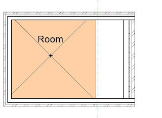
The diagrams above show what happens to the wall in section, so I have added a few snapshots of plan views to clarify (I hope) what to expect:
- Vertical wall
- Inside face of right hand wall on the reference plane
- Right hand wall Slanted 45 degrees; Location Line Inside face; zero base offset
- Note that base of wall has not moved (on the reference line):
- Right hand wall Slanted 45 degrees; Location Line Wall Centreline; zero base offset
- Note that the inside face of the base of the wall has moved slightly to left (in fact whole wall has moved) - due to pivot point being centre of wall):
- Right hand wall Slanted 45 degrees; Location Line Inside Face; 700mm base offset
- Base of wall moved 700mm to right
- Apparent wall location is the same as the wall with zero base offset - but that is what happens at the cut plane height only (a notional drawing convention). The important thing is that the base of the wall should not move when you slant the wall, but it does.
Conclusion:
Should I have done some beta testing and warned the software developers that this was not acceptable behaviour?
I have tried that with several new features in the past - sometimes they have modified things accordingly, but often not. Often the beta testing process comes too late in the development cycle, and things like that cannot be changed before release.
Either way, I think it is wrong and should be fixed immediately - before people start using it on real projects. Slanted walls will be scary enough without being built in completely the wrong location.
Next blog post I will be investigating slanted walls and room extents
And following that, 'Why the wall joins don't work in plan' . . . .


No comments:
Post a Comment