BILT Speaker

BILT Speaker
RevitCat - Revit Consultant

Thursday, 28 May 2020

Revit Callout Crop Boundary Mismatch


When placing callouts in Revit, it is a common situation that you might want the crop boundary on the callout view to be different to the view reference on the parent view.  Here is a typical example:
  • When a callout (eg. for a bathroom) is created, you typically leave a large zone around the walls so that the callout is clearly visible on the plan

  • When you go to the callout view, it has greater extents than required
  • If you adjust the crop in the view to be tight around the walls, to display as you'd typically like it on the drawing sheet . . .
  • it also affects the parent view callout reference - so the callout boundary is very hard to see on the drawing.

This is how Revit callouts were designed to work - but it does not allow you the flexibility to make your drawings look neat and readable.


The workaround solution that I would normally recommend is to create the bathroom layout views without usng the Callout tool (duplicate views, crop manually); crop them as desired; then use Callouts with 'Reference Other View'.
  • This allows you to have slightly different callout and view crop boundaries
  • Be warned that it does mean that the callouts will not automatically update if the view crop boundary is changed.

 More detail on this technique in a following blog post . . .

Monday, 25 May 2020

Weird Callout Behaviour in Revit

A few months back I wrote about some of the weird rules for Revit Callouts when you use the 'Reference Other View' option.

There are some strange and frustrating restrictions, which mean you need to plan carefully about what view types/families to use for callouts, and in fact for any views.

There are also some weird restrictions in how Callouts work when you don't use 'Reference Other View' - I refer to those as "Real Callouts".  I am going to record those here.

Stop and Think - Which Parent View?

Before placing any "Real Callouts",  stop and think about which view you want to place the callout on - you should already have a good plan for how your drawing set referencing is going to work.

The reason for this is that once you place a Real Callout on a view, it does two things:
  • It creates a new view that is automatically cropped to the extents of the callout that you just created.
  • It places the callout element on your view - typically a dashed line rectangle with a circular reference bubble.
It is  really important to know that once you place a Real Callout on a particular view, it can never be moved to another parent view.

The only workarounds are:
  • Start from scratch - delete the callout + view, which means losing all your annotation and any other reference callouts to that view.
  • Hide the callout on the parent view, and make a Reference Callout on another parent view.  This means that the old parent view can never be deleted - you would lose the callout view (refer to Deleting Callouts below). 
    This is a last resort workaround that I would not recommend.

Callout View Families

Detail Views vs Plan Views

The first issue to watch out for when creating Real Callouts is which view type you select (or don't select if you just accept the default).  For plan callouts you have two family options (and then choices of any view types that you have created):
  • Detail Views
  • Floor Plan Views

The really important thing to know here is that once you have made a decision between Detail or Floor Plan family, you can never change your mind - the families are not interchangeable.

View types are changeable - so you can change a callout from one plan view type to another plan view (but not to a Detail view).

Once you have chosen a callout view family/type, there are many weird and inconsistent rules about which view families can be referenced to and from callouts - refer to weird rules for Revit Callouts for 'Reference Other View'

For those and other reasons, I normally try to avoid using Detail views at all in Revit - see more reasons below, and refer to Weird Stair Path Stuff.

Detail Views vs Section Views

When creating Section view Callouts you also have two family options (and then choices of any view types that you have created):
  • Detail Views
  • Section Views
Unlike plan details, section details can be changed to normal section views - this is inconsistent, although it is welcome not to have that restriction.


Weird Detail View Behaviour

Detail views behave quite differently to other view types:
  • Plan and Section views are typically grouped together in the project browser - it does not distinguish between them.  This can be confusing when searching for views.
  • Detail views can be rotated in section (or elevation) from a vertical (section) orientation to a plan orientation.  If you know what you are doing you can use this to your advantage - but is not advised for inexperienced users.  It will most likely cause much confusion.
  • When creating Real Callouts from a Detail view, they can only be another detail view.
  • Stairs and railings are displayed as cut 3D models (wherever the view cutting plane is), rather than the Revit conventional 2D representation on other plan views - refer to True 3D Stair View in RCP.
  • Symbols nested into families (such as electical fittings - switches, power outlets) are not visible in Detail views.
  • Section and Plan Detail Callouts have the ability to set the depth of view the same as the parent view or independently - however, the controls are by 'Far Clip Offset' for both section and plan, not by view range.


Plan Detail Views

Plan Detail views have special rules (different to Section Details):
For Plan Detail views, the callouts are generally only visible in the views they are placed on, with one exception:
  • There is a ‘Show In’ property that can override this behaviour
  • Plan callout views are normally set to Show In ‘Parent View Only’ 
  • If this is changed to ‘Intersecting Views’ then the callout can potentially be visible in other plans within the same view range (thus behaving more like section detail callouts) - be warned, this will confuse the heck out of most Revit users.
  • Be aware that ‘Intersecting Views’ detail plan callouts can also be visible in sections – they may appear as a line or with a reference head depending on the properties of the plan view


Section Detail Views

Section Detail callout views are potentially visible in section views other than their parent view.  They behave as if they have a hard-coded 'Show in Intersecting Views' property.  They might be visible under the following conditions:
  • The callout view crop boundary is wholly within the crop boundary of the other section view
  • The callout view section line is within the Clipping Distance of the other section view
  • There are no other scale-related, category visibility or filters hiding them. 

Duplicating Views

  • If you copy and paste a real callout, it actually creates a new view (and new callout).  In most cases this is not especially useful, as you are more likely to want the same reference to the original callout view - in which case it would need to be a 'Reference Other View' callout.
  • If you copy a parent view by ‘Duplicate with Detailing’ it creates a new view for each callout – each would have a different reference on the duplicatd parent view. 


Deleting Views

  • If you delete a parent view (plan or section), it will automatically delete any callouts placed on that view, and the callout views - although it does prompt you with a warning that it will delete those views.
  • There is no way around this because once a callout is placed on a particular view, it cannot be moved to another parent view.
  • This is a major drawback to using callouts in Revit.

Next Time . . .

In addition to the issues above, there is a limitation on not being able to have a callout rectangle that is slightly larger than the crop region of the callout view - thus making your drawings messy and hard to read.  Refer to Callout crop boundary mismatch


In the next blog post on this subject I will suggest an alternative working method that avoids some of these pitfalls and inconsistencies.


If you can remember all these rules and exceptions, congratulations!  Try remembering them again in a few months time.

Monday, 20 April 2020

System Volume Parameter in Generic Category Families

 Here in New South Wales, Australia, we have a planning requirement (SEPP65) to provide a certain amount of storage in multi-unit residential developments.  Some of that storage can be in the apartment itself, and some can be in storage cages/cupboards in the basement.

The storage has to be calculated by volume per apartment - this means that we have to create schedules that combine the storage cupboards in apartments with the cages in the basement.  Thus we need to create objects of different shapes and sizes in the model.

There are several ways to calculate the volumes from these objects, but surely the simplest way would be to use Revit's automatic volume calculation properties?

System Volume Property

You would think that Revit would be able to report back the volume of any object in your model.  It is a database, right?

It turns out that it can do so, to a very limited extent - and of course that leads to restrictions and frustrations.

It seems that only cetain category objects can report their volume, and then there may be further restrictions on scheduling or tagging:

By Category

  • Many of the system families do have a "Volume" property

  • But you would not want to create storage cages or cupboards by mis-using those categories?  No, you would not!
  • Logically you would use the Casework category for cupboards - but sadly that category does not have a volume property.
  • The same applies for most loadable family categories.

  • You could use the Mass category, but that is not sensible either, because that should be reserved for creating building massing models - if you start mis-using that category it will surely make life difficult (not least with visibility issues).

  • Rooms do have volume properties, although that can depend on project settings - see below.
  • Rooms are also not an ideal way to model such things as high-level storage cupboards!

  •  That leaves us with one last option (that I know of):  the Generic category.
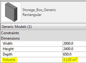
  • For many years in Revit, generic families did report a Volume property (automatically calculated from the volume of all solid objects in the family).
  • However, it was not originally possible to schedule this property
 
  • In Revit 2014, Autodesk enabled the ability to schedule this Volume property.
  • This was one of my few successes with lobbying Autodesk to include one small new feature in Revit, that would make a big difference to us.
  • Sadly they ignored my pleas to also enable this property to be tagged.

Generic Families

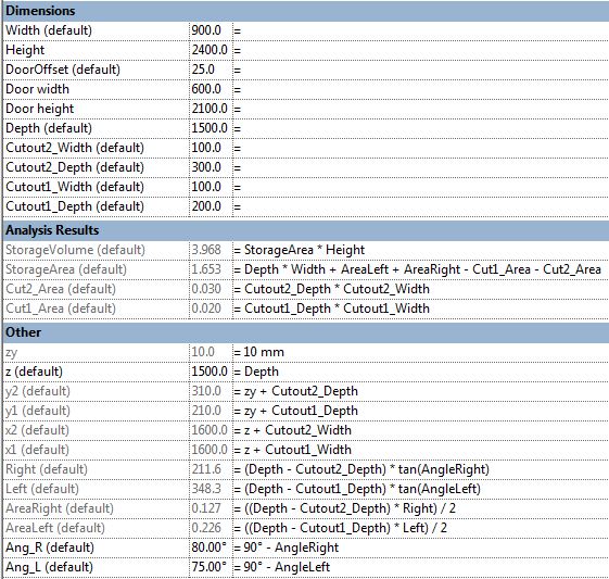
Prior to v2014, we created a range of storage families that did the volume calculations as formulas within the families - so that we could schedule and tag the volumes.

When it comes to basement storage cages, the shapes often become quite complex as they have to wrap around columns or need angled sides.


This led to some quite complex formulas that needed to take into account optional cutouts to the shapes, and to allow for overlapping cutouts.


Fortunately all these calculations became redundant with v2014, as we can now use the system calculated "Volume" parameter to schedule storage volumes.

Except . . . . . When a project requires the storage to be tagged on drawings.

Room Volumes

Rooms do have the ability to calculate and report their volume, and it may be easier to create basement storage cages as rooms with cage walls to enclose them.  This would allow any shaped area without having to create a range of families.


However, this becomes problemmatic when you need to create one schedule that combines the basement storage cages (Rooms) with in apartment storage cupboards (Generic category families).

Room volume calculations also have some quirks, that depend on project-wide settings:

  • Rooms have a height property - this is used for the system calculated volume.
  • However, it will not work if Rooms are set to only calculate Areas (not Volume)
  • This project-wide setting is generally recommended as it makes the project performance noticeably faster - the menu even tells you that (and it is true)

  • If you enable Areas and Volume calculation you will get the volumes being reported, but a slower project.
  • If you need to do this anyway, then it is no extra overhead for calculating room storage.


Room Volumes are calculated at Wall Finish, regardless of the Room Area settings.
  • This can be complicated if you need room areas to be calculated to wall centrelines.
  • More on this in another blog post . . . .

Friday, 27 March 2020

Revit Tags Label Extents and Leaders

One of the things that always annoys me in Revit is the hardcoded spacing or sizes of certain elements or settings.  These include such things as:
  • Default extension of grid lines and levels beyond a cropped view on a sheet - this appears to be just over one inch on the sheet (I was expecting it to be exactly one inch = 25.4mm).
    Why oh why does it have to be so big - all that wasted paper on plots;  or wasted time adjusting each one manually.

  •  Tag Leader Offsets - it seems the leaders go to the opposite extreme, being really tight in to the text.  If your boss does not like that graphic, you are in trouble.


Text Leader Offsets

A few years back, Autodesk actually solved a similar issue for text in Revit - although with text, prior to that the leaders had a locked in 2.032mm offset, which was equally irritating.

In Revit version 2011, Autodesk added the parameter "Leader/Border Offset", which gave us the ability to control how far the leader started from the text (even when no border was applied to the text).

Default text leader offset = 2.032mm
  • If you want the leader closer in, just change the offset to 0.5mm or 0mm

Zero mm text leader offset
 
  • If you want the leader further away, change the offset to something larger

Text leader offset 3.5mm
  • You can also add a border, which matches the leader offset exactly


The default offset in all the Autodesk templates is still 2.032mm, which is way too big.  Likewise in all projects that were upgraded in v2011, it set the value to 2.032mm.

I wonder how many BIM Managers around the world actually went in and set the value to a sensible number?  I like it to be say 0.5mm, but some people like 0mm.

Tag Leader Offsets

Sadly, Autodesk never finished that task (now where have you heard that before?).

Text labels inside tags do not follow these rules – leader offset makes no difference unless the tag-label has a border enabled.
Without a border, the leader just uses the extents of the tag family, and it considers tag-text with no border to have an offset of zero regardless of what it is set to.

For some reason the vertical and horizontal offsets are not consistent. If the leader is pointing up or down the offset is visually acceptable, but when it is left or right it is just a bit too small an offset, and looks wrong. 

  • With no border and a large leader offset the leader is tight in to the text label
Tag label leader 3.5mm no border

  •  With a small leader offset the leader is still tight in to the text label
Tag label leader offset 0mm no border
  •  The tag looks exactly the same (no leader offset)
Tag label leader 3.5mm no border


  •  As soon as you add a border, the leader offset matches that border (as per text)
Tag label leader 3.5mm


This is yet another little inconsistency in Revit to irritate you. 

Does anyone know a way to address this?

Nasty Workaround

I hate to suggest this, but if your job depends on it you could try adding a border to the tag label and make it white, so it does not show on a plot/pdf (in label Type properties).  Interestingly, the text remains black.


But we all know what kind of trouble that might cause later on . . .


Monday, 3 February 2020

Room Bounding Structural Column Materials in Revit


I recently discovered yet another obscure, hidden away setting in Revit - when I was investigating the "Room Bounding" property of different elements.

It seems that some structural columns have a "Room Bounding" property - but not all.
This has to be one of the weirdest, arbitrary decisions made by the Revit programmers:

Material for Model Behaviour

Structural columns have a weird property - so obscure and arcane, not to mention hidden away.
'Material for Model Behavior'

This property that can only be set in the Family Editor – in ‘Family Category and Parameters’: ‘Material for Model Behaviour’.


It can be one of 5 settings, each of which enables different properties and behaviour in the model:
  • Steel
  • Concrete
  • Precast Concrete
  • Wood
  • Other
Depending on which one you choose, it will enable properties in the family.
  • Steel has Connection properties
  • Concrete & Other have Rebar properties
 

These settings are hidden away behind the 'Family Category and Parameters' settings - in the project there is no way to tell which setting the family has, apart from the specific properties displayed.

You would have thought that this only affects structural engineers?

But wait.  It affects architects too . . . . .
  • Concrete has ‘Room Bounding’ properties (it is the only one that does)


Why, oh why are wood and precast concrete not room-bounding?  There are a huge number of timber structures around the world that provide perfectly good enclosures.
Wouldn't it just have been easier to make all columns potentially enclose rooms, instead of hard-coding someone's bizarre ideas about how a building might work?

Room-Bounding

When working in a project, and you discover that a 'Room' is not enclosed when you expect it to be, this is one of many things to check.
There are some other quirky Room-Bounding behaviours in Revit, to be detailed later  . . .