BILT Speaker

BILT Speaker
RevitCat - Revit Consultant

Friday, 22 January 2021

Revit Stair Wall Joins in Section

Following on from an earlier post about joining stairs and floors, I just wanted to clarify what happens when you try to join Stairs and Walls in section . . . .

We saw previously that Revit does have some limited capability to join stairs and floors at the base of a stair - but it has many limitations.

Joining a Wall and a Floor

All good Revit users would know that if a floor and a wall are of the same material, and they have coincident or overlapping edges, they can be "joined" in the model.  This is not just a graphic tool that is done per view - it affects the model in potentially all views, including material quantity schedules.  If an overlapping wall and floor are joined, the volume of material that was previously counted twice is corrected after the join so it is counted once.

Join Geometry


Select floor and wall to join
Providing that the elements are of the same material, the line between the floor and wall disappears.  In this example, the 'Level' line is revealed, as it happens to align with the top of the floor.

Joining a Wall and a Stair Landing


Try the same thing with a wall and a stair landing . . .


What happens?  Absolutely nothing.  After selecting the wall, Revit will not even highlight the stair landing (or vice versa if you select the landing first).

Well, that is just plain ridiculous!  You might argue that the wall and landing would be cast separately on site, so there should always be a joint line between them - but the graphic convention is to not show a line, or at least show a thinner line between them in section.


What to Do?

There is no good workaround to this problem - each method is clunky and not robust.

Linework Tool


Linework Tool

If you try the linework took, you immediately discover that it will not do the job for you, as it affects the whole wall.


That isn't very helpful, as you only want a small segment of the wall edge line to be invisible (or thin line).

Another strange Revit quirk with the linework tool is that when you select a line in elevation (or projection in plan) it gives you blue dots at each end , which can be dragged so that only part of the line has its style overridden.  That is a very useful capability - but infuriatingly, it does not work on cut lines.


Yet another quirk is that the underside of a run is treated as one line when cut (section), but in elevation, each step is a separate line segment.  Why, or why?

Filled Region

Filled Region
A common method of hiding a multitude-of-sins in Revit is to use Filled Regions.  These have pros and cons:

  • They are quick and easy to understand for most users
  • Their edge lines can be of different styles, including "invisible" as part of the sketch - so they hide model lines underneath 
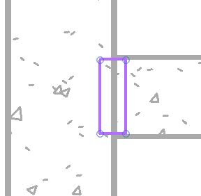


  • They will merge with underlying element hatching , providing the material hatch style matches the filled region hatching


  • They are view-based, so any patching up on one view will not show on other views
  • Line edges/junctions can be messy when viewd close-up

  • If the model is changed, the filled region will not change with it (unless you constrain the sketch lines, which is not generally advisable - as your model very quickly becomes over-constrained and unworkable)

Cut Profile

Cut Profile (View Menu)
You could try the 'Cut Profile' command - this allows you to modify how an element looks in a particular view.  Once initiated, it takes you into sketch mode - so you can draw a shape to add to an element (or cut from it).

The end result is not very promising in this situation

  • The added shape does not obscure the wall line in the way that a filled region does
  • The sketch lines cannot have a line style (unlike Filled Regions)
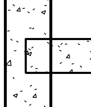

The worst thing about this idea is that the Linework tool does not work at all on cut-profile shapes - thus making this tool almost useless!

Conclusion

Sadly there is no clever workaround.  The conclusion is that it is not worth fighting Revit on this one - just accept the joint line between wall and landing.  In many cases it is not an issue, but when the stair and wall are both cast in place concrete, it is very annoying.

Tuesday, 1 December 2020

Stair Section Detail Level in Revit

Here is yet another problem with Revit Stairs that really needs to be fixed by Autodesk:  

The view 'Detail Level' display in section is not consistent between walls, floors and stairs (not to mention ramps!):

View Detail Level


When a view is set to Medium or Fine detail level, sections of most categories display the correct materials:

When the View detail level is set to 'Coarse', the cut hatching display of some elements is overridden by the Type properties 'Coarse Scale Fill Pattern'

This capability is available only for certain categories - meaning that the display of stairs is pretty hopeless at Coarse scale


Workarounds

What to do about this?  There are several possible ways to resolve this lack in Revit, but none is very good!

Visibility Graphics

You can over-ride the cut pattern of stairs - but this requires several steps (excuse the pun) on top of just changing one View Detail Level setting:

Due to the fiddly nature of changing this in the view (similar settings may need to be applied to other categories), you would certainly need to include this as part of a View Template - so it could be applied or removed at the flick of a switch.

Filters

You could also try using a View Filter, as it could potentially be applied to multiple categories

This has an advantage in that it is more "discoverable" than searching through all the category overrides - unless you have a gazillion filters applied!

Another advantage in Revit 2021 is the ability to "Enable" or "Disable" the filter without losing the override settings - a very useful new enhancement for Filters.

Downsides

The View Detail Level is very easy to switch on/off - and it affects all categories that have the built-in Coarse Scale override capability.  If you set the view back to Medium, the 'by category' cut pattern overrides get left behind - so you would need another operation to remove those (hence the need to use View Templates).


Another problem with the Visibility Graphics workarounds is what happens when you choose anything other than black solid fill as your hatching override:

If you make it grey . . .


The Stairs will show the joint lines between different materials - you may or may not want this, but it is clearly different behaviour to the Coarse Detail Level control that hides the material join lines and treats it as one material, for a nice clean look.

Of course, this is not helped by the inability to join walls/floors to Stairs !!  You still get the joint lines between those.  Refer to Stair Joint Lines

The Worst Workaround

Filled Regions are extremely useful for patching up Revit's inadequacies, but they are not popular with BIM & Model Managers because they cause so many other problems as soon as a model changes.

Filled Regions allow you to make the hatching look exactly how you want, because they allow some of their edges to be "Invisible Lines" - thus they can appear to join with adjacent "real' cut hatching.

Filled regions are placed per view, so if you have multiple sections cutting through the same or similar parts of the model you may end up with many filled regions.

One possible method to manage that problem is to include them in 'Detail Groups' - but they are also problematic to manage, not to mention a major shortcoming of really slowing down your Revit model if you have too many of them.

Conclusion

Whichever workaround you use the most important thing to do is to follow company standard procedures - and be consistent.  Agree with your workmates on which dodgy workaround to use, and stick to it.  This will make it so much easier to come back to make changes when the model is updated.


Friday, 13 November 2020

Revit Stair-Floor Joins in Section

The inability of Stairs to properly join to floors (or other elements) in Revit has long been on the wishlist of things for Autodesk to fix.  Back in v2014, we were very excited when Autodesk included this in the list of enhancements to be released.  As per many recent Revit enhancements, this was only a partial improvement.

You can be the judge as to whether it was "fixed" but most Revit users are not even aware that anything changed in version 2014, such was the hit-and-miss nature of the improvement . . . .

Join Geometry - Stairs in Section


At the base of a stair, if a concrete monolithic stair sits on a concrete floor, you would expect to be able to join them, providing they are of the same material.

Well, you can  . . . .  sort of.  It only works if the stair base is sitting exactly on the slab . 

Join Geometry


The circumstances in which it works are limited, as you can see below:  

  • If the base of the stair overlaps the floor at all, it won't work - the join is ignored.
  • OK, you wouldn't normally lower your stair like this as the base riser height would be wrong
  •  But you might extend the run lower, by selecting the "Run" (not the whole stair) and changing its 'Extend Below Riser' property
  •  The join still does not work

  • So why would you want the stair to overlap the floor?
  • Well, maybe you have a screed on the floor slab, and you want the concrete stair to rest on the slab, not on the screed.
  • With the stair sitting on top of the screed, the join does work, although it shows a thin line due to different materials - but the structural geometry is not what you want

  • As soon as you lower the base of the run, the stair cuts through the screed as it should, but the join stops working - there is a heavy outline between the stair and the concrete slab (same material).

  • Many experienced Revit users might want to separate the structural slab from the floor finish (screed) - particularly when producing 'concrete setout' drawings or when collaborating between architects and structural engineers.
  • The concrete slab could be set down by 50mm (screed thickness);  
    • Extend the run 50mm below the finished floor level;
    • Join the stair and structural slab 
    • Add a separate floor on top of the slab - just containing the finish (screed)
  •  Not surprisingly the finished floor will run through the stair

  • The stair will obviously not join properly with the floor finish as they overlap each other

Workaround

  • Just for due diligence, I thought I should test the process by trying to join the stair and the floor finish
  •  This time it actually gave a warning, saying that they cannot join

  • Much to my amazement Revit did actually join the stair to the floor finish, exactly how it ought to - despite the warning !

  • Just to make sure, I had a look in 3D - and it really had cut out the floor finish - albeit with a permanently attached warning in the list.

  • I think I could live with that warning, along with the hundreds and thousands of other spurious ones that we are unable to remove or flag as not significant.

Edge of Slab Join

In some situations, the bottom of the stair could meet the edge of the floor slab


  • Obviously the stair run needs to extend below until it meets the slab edge

  • Join Geometry ought to merge the two elements

  • Apparently it does not.

Workaround ?

Oops, sorry I don't have a real workaround for this one.

You could try using the linework tool with invisible lines, but that has annoying limitations:

  • In section, the linework tool does not have grip handles at the end of selected cut lines - it makes the whole line invisible [Lines that are in surface/projection in the view would hav grip handles so that you could make part of the line invisible]

Then you would have to add detail lines back to the missing parts of the cut edges.


Top of the Stair?

What happens at the top of a stair when you try to join it to a floor/landing?  That is a whole different story, for another blog post . . . .


Thursday, 8 October 2020

BIMAfterDark Presentation - NURBS in Revit

 Ever wanted to create vegetables in Revit?  No, well, what about curvy furniture?


 Organic Shapes using #NURBS in #Revit.

I will be presenting as a guest speaker on #BIMAfterDark Live (The RevitKid).

  •  7.30pm US Eastern Daylight Time 8th October 2020.

Or 

  • 10.30am Australian Eastern Daylight saving time 9th Oct 2020. 
  • Or watch it later

Here is the link on YouTube Live: https://youtu.be/VUkM7I1tiTs