BILT Speaker

BILT Speaker
RevitCat - Revit Consultant

Sunday, 18 March 2012

Space Planning in Revit

Below is another video of something that I talked about briefly in my presentation at the Revit Technology Conferences in 2011.

Space Planning in Revit
I created a series of adaptive components that represented corridors loaded with rooms - these could be hotel rooms or healthcare facilities. 


Using the adaptive points, it is possible to stretch and move the hotel wings around very quickly and easily;  it gives you warnings if the corridors get too long; and at the same time it maintains a schedule of room types and numbers.


If you want to see more of this kind of stuff, plus further developments of the techniques I will be presenting again at the Revit Technology Conferences this year:
RTC Australasia, Wollongong (just outside Sydney) - 24-26 May 2012
RTC USA, Atlanta, Georgia - 28-30 June 2012

Saturday, 17 March 2012

Troubles with overlapping pads in Revit

Have you ever hasd that infuriating message about not being allowed to have overlapping pads in Revit?  Why should it matter?  It would be so much easier if the lower pad took precedence in the overlapping area, and just cut into the topography.  Well that is not the way that the software is written, so here is the technique that I use to get around the problem:
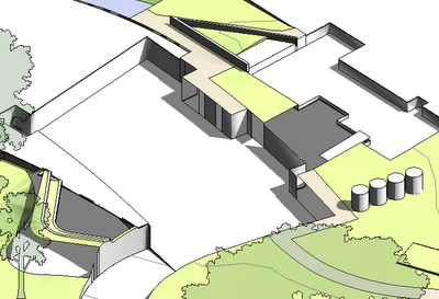
Pads at different heights cutting into a Site terrain (building hidden) 
You can see from the image above that the building being modeled has a basement over part of its floor area, so a pad is required for the basement, and then other pads are required for the various different heights of floor slabs at ground level.  Some of the pad edges need to be curved.

Option 1.
To make sure that the pads don't overlap, you could try creating the basement one first, and copy the sketch lines (to clipboard);  then start the next pad and paste the sketch lines in the adjoining area where they share a boundary, before completing the rest of the sketch.  Well, this can work sometimes, but usually not if any of the shared boundary between pads contains arcs - Revit usually considers two adjoining pads to overlap even if the adjoining boundary is one arc of exactly the same radius in the same place (perhaps it segments the arcs but does it differently for each pad?  Who knows, but it does not work).  You could try segmenting the arcs yourself to ensure that copy and pasting lines works.

Another problem with this method (assuming no arcs), is that when it comes time to change the pads you have to do a lot of double handling with temporary changes, copying lines between pads, then final changes, all to avoid any overlaps during the change process. 

Option 2.
A much better solution is to create Reference Planes along the common boundary lines between each pad, before creating the pads.  Then, when sketching the pad boundaries, you need only to pick the reference lines and lock to them (and trim the corners).  This will ensure that the boundaries do not overlap.  Another big advantage is that when you want to change the pad, all you need to do is move each reference line, and it will alter both pads at the same time, ensuring that you don't get those annoying messages - and you don't even need to go into edit/sketch mode for the pads.
   
Reference planes define boundaries for pads
You might want to put the reference planes into a workset that has its visibility hidden by default so that they don't clutter the screen, and so that they don't get accidentally deleted.  Just to be sure, you might also name the reference planes (pad boundary 1, pad boundary2 etc) so that your users know what they are for.

When it comes to arc segments of adjoining pads, you can use the same technique providing the extent of the arc segment is identical in length (as well as radius).  Obviously you cannot create curved reference planes so you'll need to use another technique - perhaps a gridline or just a line (model or annotation).

I hope this saves as much time for any readers here as it has for me.

Monday, 12 March 2012

Changing category of just one type in a Revit family

I recently had a tricky little Revit problem to solve, so I thought I would share the workflow that I devised to achieve it.  We have a "non-specific" joinery family that is basically just a box, that can be used quickly in early stages of modeling - it has a category of "Casework".  The only problem is that it sometimes gets overused  to represent boxy objects that should be of another category.  A case in point occured when someone used it to represent solar panels on a roof.  I actually have a solar panel family that has an adjustable angle for the top surface, and it calculates the top surface area so it can be scheduled to give a total panel area for the roof - it is of the category "Specialty Equipment".  We needed to swap the wrongly placed casework boxes over for the specialty equipment panels - simple job I thought.  Until I tried it and remembered that Revit won't even list the specialty equipment families when you select an already placed casework component, let alone allow you to swap it over.  So, how to achieve it ?

There is a workaround that allows you to change the category of a family - just select one, edit family, change its family category and reload.  But that would mess up all the legitimately placed joinery boxes in the project.  So I took that process a step further:

  1.  Select one of the boxes on the roof; edit its family;
  2. Save it with a temporary name;
  3. Set its default instance parameters as you wish to use on the solar panels (optional);
  4. Load it back into project (it will not overwrite anything);
  5. Select all the ones you want to change - eg, select 'all instances in view' on the roof plan;
  6. Swap all of them to the temp family.
  7. Go back to the family editor;
  8. Change its category using the "Family Category & Parameters" icon 
  9. Load it back into project;
  10. It will overwrite the temporary family and in the process happily change its category to the one you selected (Specialty Equipment in this case);
  11. Select all instances of the temporary family and change to the other family/type of that category (eg Solar panels) – it will now let you do so as they are same category;
  12. NB. if the parameter names are the same, hopefully it won't mess with the instance values.  If it does, try undo, and resetting the default values in the solar panel family to what you want before loading the family into the project. 
  13. Delete/purge the temp family from project.
You obviously need to be a little careful and follow the process rigorously. 

Here is another tip regarding categories (documented, but worth repeating):

If you plan to change categories of a family, it will appear to wipe out the sub-categories - but actually they are still there, hidden away;  they may show up in the project listed under the old category in Visibility Graphics.
To avoid this:
  • Go to Object Styles in the family editor – check for sub-category names;  if you have any, make a note of them, then check which objects use that sub-category; 
  • Delete the sub-category from Object Styles (because otherwise it will vanish at next stage but stay in memory, hidden).
  • Change the category of the family;
  • Go to Object Styles again – add the sub-category name(s) back in, under the new category;  
  • Select the relevant elements and change them to that sub-category.

Monday, 20 February 2012

Two-Directional Arrays in Revit - Some Detail

As promised last month, here is a little more detail on the techniques used to create a complex two-directional array in Revit:

The nice little four square "Array" command icon in Revit, implies that you can array elements in two directions at once.  Sadly this is not the case - so you have to resort to creating arrays in one direction, and then arraying the result in the other direction.
The first thing to know is that if you try to array elements in Revit, and then array the results as a group, you end up with nested groups.  This really does not work - you very quickly get into trouble keeping things aligned and locked, particularly when you add parameters to the mix.  The technique that I used to create the complex pattern arrays shown in earlier posts, was to nest the arrays as components rather than groups.  This gives you much better control, and avoids all those frustrating error messages.  It may seem longer to set up but it soon saves you time.

You might start with a simple component that has two options for a circle or a square (chosen by Yes/No visibility parameters):
  • This component might also have parameters for changing its size;
  • You can add a material parameter to the object so that you can later control its colour;
  • Then you need to nest the component into another family, and link its parameters to similar ones in the parent family;
  • Using reference planes to lock to, you can give it some X and Y offset parameters (as seen in the middle image above);
  • Then create multiple types for the nested component, and give each one a different value for its material, and hence a different colour;
  • This component then needs to be nested into another family.  
  • Again you need to link the parameters, but this time you need to take advantage of the new capability (in v2012) to assign types by a formula in a parameter.  This is where the control of colours is done.
  • Now you can do the first array, creating parameters to control spacing and numbers in the array (as shown in the right hand image above).
  • Time for some more nesting into another family, so that you can create arrays within arrays in the same direction (as shown below).


  • You need to link the parameters to equivalent ones in the parent again;  and then add some new parameters to control the multiple arrays;
  • Then repeat the process, by nesting again.
  • This time you can array in a different direction.


    Eventually you will end up with a very complex family nested about 6 levels deep, with dozens of parameters.  The nesting means that the family can be very slow to respond when you first place it or make any changes to it.  Of course you could create much simpler two-directional arrays that only have two levels of nesting.