 | |
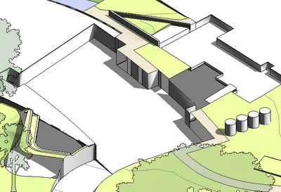
| Pads at different heights cutting into a Site terrain (building hidden) |
Option 1.
To make sure that the pads don't overlap, you could try creating the basement one first, and copy the sketch lines (to clipboard); then start the next pad and paste the sketch lines in the adjoining area where they share a boundary, before completing the rest of the sketch. Well, this can work sometimes, but usually not if any of the shared boundary between pads contains arcs - Revit usually considers two adjoining pads to overlap even if the adjoining boundary is one arc of exactly the same radius in the same place (perhaps it segments the arcs but does it differently for each pad? Who knows, but it does not work). You could try segmenting the arcs yourself to ensure that copy and pasting lines works.
Another problem with this method (assuming no arcs), is that when it comes time to change the pads you have to do a lot of double handling with temporary changes, copying lines between pads, then final changes, all to avoid any overlaps during the change process.
Option 2.
A much better solution is to create Reference Planes along the common boundary lines between each pad, before creating the pads. Then, when sketching the pad boundaries, you need only to pick the reference lines and lock to them (and trim the corners). This will ensure that the boundaries do not overlap. Another big advantage is that when you want to change the pad, all you need to do is move each reference line, and it will alter both pads at the same time, ensuring that you don't get those annoying messages - and you don't even need to go into edit/sketch mode for the pads.
 | |||
| Reference planes define boundaries for pads |
When it comes to arc segments of adjoining pads, you can use the same technique providing the extent of the arc segment is identical in length (as well as radius). Obviously you cannot create curved reference planes so you'll need to use another technique - perhaps a gridline or just a line (model or annotation).
I hope this saves as much time for any readers here as it has for me.

Thanks for tips, I like option 2
ReplyDeletebut just to be clear, are all your pads on one level?
I have this problem of making pads of different levels on one topography. I just slice topography and.... it's a mess anyway.
sometimes topography just becomes like a face without volume.
You have any tips for these too?
thanks
When you say "one level", not sure if you mean Revit level, or just one height. So they are all on the same Revit level, but with different vertical offsets - so, at different heights. Sorry, no solutions for the horrible effects you sometimes get when slicing a section through topography - it can be very unpredictable, in that sometimes a pad causes an area without cut hatching in the topography - probably a bug.
ReplyDeleteThe relationship between topographies and pads really needs a big re-think by the Revit developers.
ReplyDeleteOne that kills me is when you have a floor that cuts into the topography and becomes suspended once it leaves the ground line. You cant actually achieve that with a building pad without forcing the topography to extend up to its underside. Instead you have to manually calculate where the pad leave the ground and end the sketch at the point. This condition is a fairly typical one and Its pretty ridiculous that you cant account for it in Revit.