
Using Adaptive Components to make Mona Lisa's whole face follow you around the room

Have you ever wanted to make all your 2.5d trees or people face the camera in a perspective view in Revit? No? Well I'm going to tell you how anyway - maybe it will help someone come up with new ideas of how to use this technique.
- First create a new "Generic Adaptive Model" family;
- Place two points along the X axis;
- Select the points and make them adaptive;

- Join the points with a reference line;

- Set the workplane to be the vertical plane of the adaptive point (1) at the start of the reference lin, perpendicular to the line;


- Alternatively you can pick the end workplane of the reference line itself;
- Use model (or reference) lines to trace the 2d outline of a person;
- Select the lines and create a form - an extrusion of the person outline;

- Select adaptive point 2, move it around to flex the family;
- The person extrusion should remain perpendicular to the line, and it should rotate around to follow it (providing it was correctly associated with the work plane of point 1;

- Return the adaptive points to the x axis location;
- Add some model line detail (or more extrusions as desired), making sure that they are either hosted on the same workplane or on the form itself - in this case I have added a Mona Lisa face to make it more fun;

- Flex the family again by moving adaptive point 2, to check that all geometry is correctly associated - in this case the face rotates but Mona Lisa's eyes will keep looking at you;

- Now the Mona Lisa family is ready to use;
- Load her into a project;
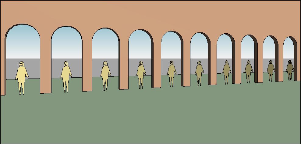
- In this example I have created a series of arch doorways;
- I have also created an object to represent the camera location - it can be any object, but the best thing would be to create a "camera family"

- Place a Mona Lisa adaptive family - first point in the middle of an archway, second point snapping onto the camera object (important, it must snap to it)

- Place a second Mona Lisa in the second archway, but snap its second point to the same camera object;
- Place as many more Mona Lisas as you need, each sharing the same second point on the camera object;

- Note how each Mona Lisa is slightly rotated, so that they are all looking at the camera object;
- Now create a camera view, ensuring that the camera location is approximately the same as the camera object;
- All the Mona Lisas will be facing the camera;
- You might argue that her eyes would have been looking at the camera without rotating the whole body - true, but this technique will work for anyone other than Mona Lisa; or for a tree or any other 2.5d (flat extrusion) entourage family;
- Create another camera view from a completely different angle;
- The Mona Lisas will no longer be facing the camera in this view

- Check this out in plan view too - they are all still facing the first camera location;

- Right-click on the second perspective view in the Project Browser, and select "Show Camera" to see where it is in plan;
- Place a marker - eg a cross in plan;

- Move the camera object to the new camera location;

- All the Mona Lisas should rotate together to face the new camera position

This may seem like a clunky workflow, but once it is set up all it requires is a single move of the camera object to each view location - so its not going to work if you have several views on one sheet.
Of course all the people don't have to look the same - they just need two adaptive points to work. Each person could have a parameter for a small rotational adjustment within the family to give some variation - each one could face slightly away from the camera, but close enough not to get any side on views of extrusions. This would ensure that the scene does not look quite so artificial.
There is an alternative method of placing the people - more on that next time.
I hope this helps someone out, or inspires some new method of improving presentation methods in Revit . . . .
Less clunky than manually rotating objects one by one. Thanks for sharing Tim.
ReplyDeleteGlad you enjoyed it Andy.
ReplyDeleteI'm not sure how many people actually want 2D people, trees, cars etc to face the camera in different views?
One thing I've had a problem with is controlling the rotation of nested families in an adaptive component - thats why I created the extrusion directly in the adaptive family.
superb
ReplyDeletenice...
ReplyDeletefor render i tried with a custom rpc family for this (billboard option does the trick to automatic follow the camera), but autodesk 360 rendering doesnt work with custom rpc content so maybe a try this (I'll wait a little for revit 2015, hopping that archivision support custom rpc families).
Hi,
ReplyDeletereally useful post, thanks for that! Really struggling to assign the extruded object to follow the adaptive point 2. Point 1 and 2 are linked and both rotate and remain perpendicular, buuut..the object stays in place ignoring the rotation. Could you share how you assigned your object to recognize that it needs to move together with the point? I tried ref planes, didn't work for me..maybe missing something out. Thanks in advance!
Best
If the object does not rotate, it probably means that you did not set the workplane to be one of the planes on point 1 - I advised the vertical plane. Alternatively you can select the vertical end plane of the reference line. If you don't host your 3d object on the point (or end of reference line) it will not rotate. Don't make the mistake of building the 3d object on the reference plane of the whole family - that is what I did the first time.
ReplyDeleteHi Revit Cat. Tank you so much for this! I have been trying to figure out how to develop my own extensive planting family pallet for a long time without having to use the expensive rcp options out there. I don't seem to be able to get the object, or even the points to follow one another despite following your instructions.
DeleteAngus,
DeleteThere are so many possibilities for what went wrong that I can't give you a simple answer, but try checking these:
Points must be adaptive (and you need to know how adaptive points work).
Join the two points with a reference line but make sure 3D snapping is on otherwise line won't link to points.
Most important is to set the workplane before placing the component - must be either work plane at end of the line (perpendicular to it) or one of the planes on the point