BILT Speaker

BILT Speaker
RevitCat - Revit Consultant

Wednesday, 27 November 2019

Weird Reference Callout Rules in Revit

Over many years of struggling with Revit's numerous quirks, I have never quite figured out what the hidden rules are for Callouts.  Here are my latest thoughts after some detailed research:

Reference Callouts


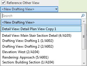
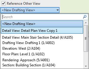
When you tick the box 'Reference Other View' you get a list of possible views to reference.  That list of views is not predictable (so I thought) - however, I've narrowed down some extra rules about which views might be available:
  • A plan, section, elevation or detail view will only show in the list if it is cropped  (This caught me out at first).
  • A drafting view cannot be cropped - so the above rule does not apply.
  • A so-called "Rendering" view, which is actually like a drafting view with an image on it- so it cannot be cropped
  • Certain view family/types are available depending on the active view being placed in - see the list below.
  • If you apply the first two rules to the list of view types below, you might just be able to predict what can be referenced when.


Rules for 'Reference Other View' Callouts:

In a floor plan view, you can reference callout to:
  • Any drafting view
  • A detail Plan view (but not a section detail view)
  • A floor plan view (including Area plan and RCP)
  • A Rendering view


In a detail plan view, you can reference callout to:
  • Any drafting view
  • Any detail view (Plan or section)
  • Any section or elevation view
  • Not to any floor plan - (this is a big limitation)
  • A Rendering view

In a section view or section detail view, you can reference callout to:
  • Any drafting view
  • Any detail view (Plan or section)
  • Any other section or elevation view (But not to a floor plan)
  • A Rendering view
 
In a drafting view (or a rendering view), you can reference callout to:
  • Any drafting view
  • Any detail view
  • Any floor plan view (including Area plan and RCP)
  • Any other section or elevation view
  • A Rendering view


However, the choice of view type is not always that simple . . . .

In a previous post (about stair path arrows) I described the relative benefits of making your plan callouts 'Plan Views' vs 'Detail Views'.

You may also want to display your stairs differently in plan (compared to the standard 2D representation in plan views):

Weirder and Weirder

For more details on Callout weirdness, refer to:

Friday, 22 November 2019

Travel Path Update in Revit 2020.2

Hooray - with the release of 2020.2, we finally have something useable in the Revit 2020 Path of Travel feature!

The initial release in Revit 2020 Path of Travel and Follow Up and the improvements in 2020.1 actually gave us a feature that was unusable in almost every situation.

It still has a number of limitations but at last we can make use of it to some degree.  What makes the big difference is the ability to add "Waypoints" anywhere along the path of travel.


You may remember (from my earlier descriptions) that when you place a 'Path of Treavel' by clicking the start and end points, Revit calculates the path for you - and you had little control over that, apart from choosing which elements form obstructions (or not).  Hence, in the standard Autodesk sample file, the path calculation was not able to determine that a sofa at a lower level should still be an obstruction:
Path or travel in v2020

In 2020.2, the calculation seems to have been slightly rationalised to give a more sensible path through the corridor to the north, but it still goes over the sofa in the split-level living area.
Path of Travel in 2020.2

Add Waypoints

We now have the ability to add (or remove) 'Waypoints' - this allows us to nudge the path to a more sensible course around the sofa.

If you need to make your path of travel orthogonal (as required in some jurisdictions), it can be done by adding enough waypoints - rather laborious but at least it works.


This is a very welcome addition to this feature.  However, it is still taking longer than the Daleks to learn how to manage stairs and changes of level in the building.
There is still no way to control the minimum width of a gap between obstacles (about 430mm or 17")

Saturday, 9 November 2019

Scope Box View Property Greyed Out in Revit

Here is a little software trick to catch out the unwary Revit user:

There are some situations where the Scope Box property of a view is greyed out - so you cannot assign a Scope Box to the view.

The answer may be to do with the Crop Boundary - and it may not be obvious, especially if the crop boundary is hidden.


To track this down:

  • Make the Crop Boundary visible
  • It may or may not be apparent that the  Crop Boundary has been edited
  •  Or it may not be obvious - if only a minor edit is done to the boundary
  • Select the crop boundary
 
  •  If it has been cropped, the Ribbon will show the 'Reset Crop' icon available
  • Another way to check if it has been cropped is to look for the shape-handles on the crop boundary - extra dots indicate segments in a boundary
  • Click on 'Reset Crop' - the edits to the boundary will be removed (along with the extra shape-handles)
  • The Scope Box property will now be available for use.
  •  The 'Reset Crop' icon will now be greyed out - indicating the crop is no longer edited.

This behaviour is quite logical once you know what is going on - but it can be confusing when you first encounter it.  Of course you do not want people to accidentally remove a Crop Boundary just by applying Scope Boxes - without realising what they have done.

Wednesday, 2 October 2019

Architectural Ceiling Plan Hidden Categories in Revit

A while back, someone asked me why some model elements remained visible when they turned off ALL Model categories in Visibility Graphics.

The list of categories that show on the Visibility/Graphic dialog box varies depending on the Discipline filters applied to the dialog box. If you are preparing a set of architectural reflected ceiling plans, you may want to show lights, sprinklers, security etc. However, not all relevant categories are shown if you only have ‘architecture’ ticked.


Watch out for hidden categories in this situation. Each user may have different discipline filters applied on their computer (it is per user in Revit, not per view).

This means that some MEP categories may not be shown in the Visibility/Graphic list – therefore the user will not be able to show/hide or override those categories.

If the user has only the Architecture discipline showing, then clicks on ‘All’, it does not include the hidden MEP categories, including:
  • Data devices
  • Fire Alarm devices
  • Nurse Call Devices
  • Security Devices
  • Sprinklers
  • Telephone Devices
I have encountered situations where frustrated users have turned off all categories, and wondered why the sprinklers remain on.  For this reason I recommend that architects should consider using only  the following categories for Ceiling and Electrical fixtures in their libraries - for architectural Revit models:
  • Electrical fixtures
  • Lighting Fixtures
  • Mechanical Equipment
  • Specialty Equipment 
Architecture Discipline Only

However, for multi-disciplinary Revit models you probably need to stick with the correct categories - obviously MEP engineers should use the correct categories for their models, because they have specific behaviour that is important to them.  In the case of separate, linked MEP models, the services engineers may be modelling their own fixtures, and using the architectral model just for coordinating ceiling fixture locations.
All Disciplines

For architects working in multi-disciplinary models, where you do need to use the correct categories for all fixtures, then you need to educate your staff about changing the filter list to show all relevant disciplines. 

What a pity that we don't have all the categories that we need - Signage for example (amongst many others missing).  However we do have at least one redundant category: Roads - we'd like to be able to use it but we have no tools to model roads with.


Monday, 23 September 2019

Inconsistent Units Settings UI in Revit


There are several very different ways of getting to Units Settings in the Revit User Interface.  Most of them are not very intuitive - and certainly they are totally different from each other.

Project Unit Settings

There are 3 different icons on the 'Manage' ribbon, depending on your screen resolution and size:

Largest resolution or screen
 If you are operating on a laptop or low resolution, the icon automatically reduces in size, and you may or may not get a text description:
Medium resolution or screen

Smallest resolution or screen

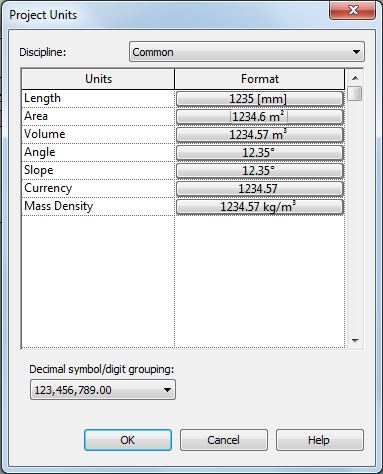
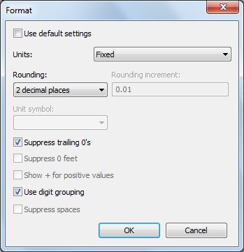
Once you click on the Project Units icon it takes you to the units dialog box, which has a list of different kinds of units:


Once you choose a particular unit type, it gives the project-wide 'Format' settings for that type.  Since this is the project settings, the checkbox at the top is greyed out.   Some of the checkboxes are related only to imperial measurements so would always be greyed out for metric users.

This dialog box is the one common UI that appears for all methods of accessing units - but different items are greyed out in each situation that the dialog box appears.


Dimension Units

  • Select a Dimension in the project 
  • Click on Edit Type


  • Click on the Units Setting property
  • This takes you to the Units Format dialog box where you can override the project settings
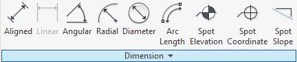
Alternatively you can access this units dialog box from the Annotation ribbon:
  • Click on the Dimensions drop-down arrow
  • Select the kind of dimension you want


Schedule Units Settings

  • In the Schedule Properties, go to the 'Formatting' tab
  • Select a field (on the left)
  • Click on the 'Field Format...' button on the right


  • Once you click on this, you get the standard Units dialog box
  • Typically the 'Use default settings' checkbox is ticked 
  • You can untick it if you want to over-ride the project settings


Tag Units Settings

Refer to Revit's Most Hidden Commands (part 2) for more detail on this.  It is quite tricky to find this setting:

  • Edit the tag family
  • Select and Edit a label

  • The parameter in the label may look like it is selected (on the left), but it is probably not
  • Select the relevant parameter (on left, even though it shows on the right)

  • The 'Properties' icon (a hand) will be enabled
  • Click on it

  • Finally you get to the units settings, which is normally defaulted to 'Use project settings'
  • It is not possible to get to this unit override setting within the project environment (unlike dimensions and schedules)

Summary

Here we have at least 4 completely different ways to access Revit units settings:

Method 1 (Ribbon in the project ):


Method 2 (Dimension Type properties in the project ):

or

Method 3 (Schedule formatting properties in the project ):


Method 4 (Tag properties in the Family Editor ):


Why does something so simple have to be so inconsistent, and complicated ?


Tuesday, 3 September 2019

Reveal Obstacles in Path of Travel - Revit 2020.1

Revit 2020.1 Enhancement

If you place a 'Path of Travel' using the new (in Revit 2020) feature, you may encounter a situation like that shown below, where the path appears to go through an object that should be an obstruction - such as the path through sofa example below:


In addition to other Revit 2020.1 enhancements to the Path of Travel feature  - Move Start/End Points, we have a new tool that may help you out:

Reveal Obstacles in Path of Travel -


This is useful for figuring out why your path of travel is not behaving as expected. 
  • On the Analyze toolbar, click on 'Reveal Obstacles'

  • This temporarily changes the view display to show in orange all categories that represent obstacles to the path.
In the example below (Autodesk sample file), some items are not shown orange
 
  • The doors are not obstacles because that category is excluded
  • Some furniture is not shown in orange (obstacle) because they are below the cut plane for calculation.  The reason is that the model is split level, and the living area is 500mm lower than the rest of the house - refer to Analysis Zone follow up for more detail on Split Levels and calculation heights.
  • In the case of the large sofa family, one part of the component shows orange - this is the high back.  This demonstrates that Revit actually analyses the geometry of elements, not just a bounding box for each component - which is a good thing.

As the sofa is much lower than the main floor level, only the back projects up into the analysis zone.
  • If the sofa is raised by 200mm (8"), then the sides of the sofa also project into the zone - they become obstacles, and hence turn orange (it may not be immediate - see glitches listed below).

However, the path itself does not change - you have to select it and click on 'Update Path' for that to happen;  then the path will go around the sides of the sofa.

Obstacle Settings

 
If you go the the Route Analysis Settings, you can add or remove obstacles by category - for example add Furniture and Casework categories to the list that are not obstacles


Initially nothing happens, but when you update the path it will no longer avoid those categories.  These will no longer be highlighted in orange by the 'Reveal Obstacles setting

Furniture no longer an obstacle

Casework category no longer an obstacle - path not yet updated

NB. There is some unexpected behaviour that can occur with the 'Reveal Obstacles' feature:
  • If you already have 'Reveal Obstacles' mode on when you go into the 'Route Analysis' settings, then change the categories - Reveal Obstacles does not update the categories displayed orange/grey (you need to turn it off then on again for a refresh).
  • If Reveal Obstacles mode is on, and you try to select an element:
    • Initially it will highlight all of the obstacles as one item;  select it and you get Analysis results Properties (see below for more details)
    • if you tab select, it highlights a component, but still considers it part of the analysis result;  Select it and you get Analysis Result listed but without any properties;
    • Tab again and it finally selects just the element - you can then change its properties;  However, the Reveal Obstacles highlighting is not updated even when it should be - eg. if the sofa height is changed to 500mm so that the whole sofa becomes an obstacle, the sofa does not turn orange (when it should).
  • If you select the whole analysis result, you get shown properties for the Analysis Result.
  • It is not immediately clear what these properties are for.
  • If you click on the 'Edit..' button (Results Visibility), as you would be tempted to do, you get some more mysterious properties
  •  Make the dialog box a fraction wider, and one of the headings shows in full:  'Analysis Display Style' - it has a hidden button to the right of <By View>

  • Click on the hidden button to reveal the Display Style dialog

  • You can play around with the text and arrowhead settings
 
  • And go to the Legend Tab
  • Click on 'Show Legend'
  • The end result means not much to me, but I'm sure it has a purpose
Arrowheads and legend displayed
  •  You can move the legend on the view, if that is what you need


I am guessing that these analysis display settings are for some other kind of analysis, but have been enabled here too?
  • I am not going down that rabbit hole today!
 

Conclusion

Sadly, useful as this new feature is, it does not address fundamental shortcomings - such as what you need to do when Revit fails to generate (or update) a path at all.

We need more help to be able to deal with that situation, as the Warning dialog box is not at all helpful!