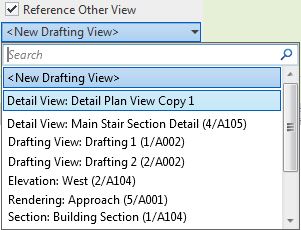
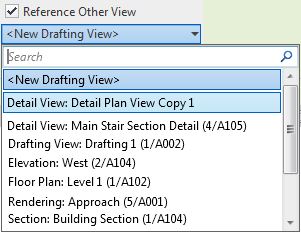
Over many years of struggling with Revit's numerous quirks, I have never quite figured out what the hidden rules are for Callouts. Here are my latest thoughts after some detailed research:
When you tick the box 'Reference Other View' you get a list of possible views to reference. That list of views is not predictable (so I thought) - however, I've narrowed down some extra rules about which views might be available:
However, the choice of view type is not always that simple . . . .
In a previous post (about stair path arrows) I described the relative benefits of making your plan callouts 'Plan Views' vs 'Detail Views'.
You may also want to display your stairs differently in plan (compared to the standard 2D representation in plan views):
Reference Callouts
When you tick the box 'Reference Other View' you get a list of possible views to reference. That list of views is not predictable (so I thought) - however, I've narrowed down some extra rules about which views might be available:
- A plan, section, elevation or detail view will only show in the list if it is cropped (This caught me out at first).
- A drafting view cannot be cropped - so the above rule does not apply.
- A so-called "Rendering" view, which is actually like a drafting view with an image on it- so it cannot be cropped
- Certain view family/types are available depending on the active view being placed in - see the list below.
- If you apply the first two rules to the list of view types below, you might just be able to predict what can be referenced when.
Rules for 'Reference Other View' Callouts:
In a floor plan
view, you can reference callout to:
- Any drafting view
- A detail Plan view (but not a section detail view)
- A floor plan view (including Area plan and RCP)
- A Rendering view
In a detail plan
view, you can reference callout to:
- Any drafting view
- Any detail view (Plan or section)
- Any section or elevation view
- Not to any floor plan - (this is a big limitation)
- A Rendering view
In a section
view or section detail
view, you can reference callout to:
- Any drafting view
- Any detail view (Plan or section)
- Any other section or elevation view (But not to a floor plan)
- A Rendering view
In a drafting view (or a rendering view), you can reference
callout to:
- Any drafting view
- Any detail view
- Any floor plan view (including Area plan and RCP)
- Any other section or elevation view
- A Rendering view
However, the choice of view type is not always that simple . . . .
In a previous post (about stair path arrows) I described the relative benefits of making your plan callouts 'Plan Views' vs 'Detail Views'.
You may also want to display your stairs differently in plan (compared to the standard 2D representation in plan views):
Weirder and Weirder
For more details on Callout weirdness, refer to:


